Infiniti M35/M45 Y50. Manual - part 956


  Index      Infiniti     Infiniti M35/M45 Y50 - service repair manual 2007 year


Search            copyright infringement  


Content   ..  954  955  956  957   ..


Infiniti M35/M45 Y50. Manual - part 956


ENGINE MAINTENANCE (VQ35DE ENGINE)

MA-21

C

D

E

F

G

H

I

J

K

M

A

B

MA

INSPECTION AFTER REMOVAL

Use the standard type spark plug for normal condition.
The hot type spark plug is suitable when fouling occurs with the standard type spark plug under conditions
such as:

Frequent engine starts

Low ambient temperatures

The cold type spark plug is suitable when spark knock occurs with the standard type spark plug under condi-
tions such as:

Extended highway driving

Frequent high engine revolution
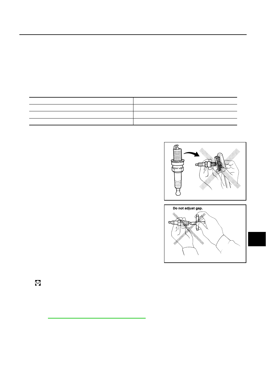
CAUTION:

Do not drop or shock spark plug.

Do not use a wire brush for cleaning.

If plug tip is covered with carbon, spark plug cleaner may
be used.

Checking and adjusting plug gap is not required between
change intervals.

INSTALLATION

Install in the reverse order of removal.

Checking EVAP Vapor Lines

NLS0007P

1.

Visually inspect EVAP vapor lines for improper attachment and for cracks, damage, loose connections,
chafing and deterioration.

2.

Inspect fuel tank filler cap vacuum relief valve for clogging, sticking, etc.
Refer to 

EC-39, "EVAPORATIVE EMISSION SYSTEM"

 .

Make

NGK

Standard type

PLFR5A-11

Hot type

PLFR4A-11

Cold type

PLFR6A-11

Gap (Nominal)

: 1.1 mm (0.043 in)

Cleaner air pressure:

Less than 588 kPa (6 kg/cm

2

 , 85 psi)

Cleaning time:

Less than 20 seconds

SMA773C

SMA806CA

: 24.5 N·m (2.5 kg-m, 18 ft-lb)

MA-22

ENGINE MAINTENANCE (VK45DE ENGINE)

ENGINE MAINTENANCE (VK45DE ENGINE)

PFP:10001

Checking Drive Belts

NLS0007Q

WARNING:

Be sure to perform when the engine is stopped.

Remove air duct (inlet) when inspecting drive belt for alternator, water pump and A/C compressor.

Remove front engine undercover with power tool when inspecting power steering oil pump belt.

Make sure that indicator (single line notch) of each auto tensioner is within the allowable working range
(between three line notches).
NOTE:

Check auto tensioner indication when engine is cold.

When new drive belt is installed, the range should be “A”.

The indicator notch is located on the moving side of the tensioner for alternator, water pump and A/C
compressor belt, while it is found on the fixed side for power steering oil pump belt. 

Visually check entire belt for wear, damage or cracks.

If the indicator is out of allowable working range or belt is damaged, replace belt.

Tension Adjustment

NLS0007R

Belt tensioning is not necessary, as it is automatically adjusted by auto tensioner.

Changing Engine Coolant

NLS0007S

WARNING:

To avoid being scalded, do not change engine coolant when engine is hot.

Wrap a thick cloth around radiator cap and carefully remove radiator cap. First, turn radiator cap a
quarter of a turn to release built-up pressure. Then turn radiator cap all the way.

Be careful not to allow engine coolant to contact drive belts.

DRAINING ENGINE COOLANT

1.

Remove engine room cover (RH and LH) Refer to 

EM-173, "ENGINE ROOM COVER"

 .

2.

Remove engine cover with power tool. Refer to 

EM-179, "INTAKE MANIFOLD"

 .

3.

Open radiator drain plug at the bottom of radiator, and then remove radiator cap. 

PBIC3822E

ENGINE MAINTENANCE (VK45DE ENGINE)

MA-23

C

D

E

F

G

H

I

J

K

M

A

B

MA

When draining all of engine coolant in the system, open water drain plugs on cylinder block. Refer
to 

EM-253, "DISASSEMBLY"

 .

4.

Remove reservoir tank as necessary, and drain engine coolant and clean reservoir tank before installing.

5.

Check drained engine coolant for contaminants such as rust, corrosion or discoloration.
If contaminated, flush the engine cooling system. Refer to 

MA-24, "FLUSHING COOLING SYSTEM"

 .

REFILLING ENGINE COOLANT

1.

Install reservoir tank if removed, and radiator drain plug.

CAUTION:

Be sure to clean radiator drain plug and install with new O-ring.

If water drain plugs on cylinder block are removed, close and tighten them. Refer to 

EM-257,

"ASSEMBLY"

 .

2.

Make sure that each hose clamp has been firmly tightened.

3.

Remove air relief plug (1) on heater hose.

4.

Fill thermostat housing and reservoir tank to specified level.

Refill engine coolant up to filler neck of thermostat housing.

Pour engine coolant through engine coolant filler neck slowly of less than 2   (2-1/8 US qt, 1-3/4
Imp qt) a minute to allow air in system to escape.

Use genuine NISSAN Long Life Antifreeze/Coolant or equivalent mixed with water (distilled or
demineralized). Refer to 

MA-12, "RECOMMENDED FLUIDS AND LUBRICANTS"

 .

1

: Radiator drain plug hole

2

: Front engine undercover

: Engine front

PBIC3395E

Radiator drain plug:

: 1.2 N·m (0.12 kg-m, 11 in-lb)

: Engine front

PBIC3394E

Engine coolant capacity 
(With reservoir tank at “MAX” level):

Approx. 10.4   (11 US qt, 9-1/8 Imp qt)

MA-24

ENGINE MAINTENANCE (VK45DE ENGINE)

When engine coolant overflows air relief hole on heater hose,
install air relief plug.

5.

Install radiator cap.

6.

Warm up until opening thermostat. Standard for warming-up time is approximately 10 minutes at 3,000
rpm.

Make sure thermostat opening condition by touching radiator hose (lower) to see a flow of warm water.

CAUTION:

Watch water temperature gauge so as not to overheat engine.

7.

Stop engine and cool down to less than approximately 50

°

C (122

°

F).

Cool down using a fan to reduce the time.

If necessary, refill engine coolant up to filler neck of thermostat housing.

8.

Refill reservoir tank to “MAX” level line with engine coolant.

9.

Repeat steps 4 through 7 two or more times with radiator cap installed until engine coolant level no longer
drops.

10. Check cooling system for leaks with engine running.

11. Warm up engine, and check for sound of engine coolant flow while running engine from idle up to 3,000

rpm with heater temperature controller set at several position between “COOL” and “WARM”. 

Sound may be noticeable at heater unit.

12. Repeat step 11 three times.

13. If sound is heard, bleed air from cooling system by repeating steps 4 through 7 until engine coolant level

no longer drops.   

FLUSHING COOLING SYSTEM

1.

Install reservoir tank, and radiator drain plug.

CAUTION:

Be sure to clean drain plug and install with new O-ring.

If  water drain plugs on cylinder block are removed, close and tighten them. Refer to 

EM-257,

"ASSEMBLY"

 .

2.

Remove air relief plug (1) on heater hose.

3.

Fill thermostat housing with water until water spills from the air relief hole, then close air relief plug. Fill
thermostat housing and reservoir tank with water and reinstall radiator cap. 

Reservoir tank engine coolant capacity
(At “MAX” level):

0.8   (7/8 US qt, 3/4 lmp qt)

Air relief plug:

: 1.2 N·m (0.12 kg-m, 11 in-lb)

SMA412B

Radiator drain plug:

: 1.2 N·m (0.12 kg-m, 11 in-lb)

: Engine front

PBIC3394E


Content   ..  954  955  956  957   ..