Infiniti M35/M45 Y50. Manual - part 954


  Index      Infiniti     Infiniti M35/M45 Y50 - service repair manual 2007 year


Search            copyright infringement  


Content   ..  952  953  954  955   ..


Infiniti M35/M45 Y50. Manual - part 954


RECOMMENDED FLUIDS AND LUBRICANTS

MA-13

C

D

E

F

G

H

I

J

K

M

A

B

MA

Engine Oil Recommendation

NLS0009X

NISSAN recommends the use of an energy conserving oil in order to improve fuel economy.
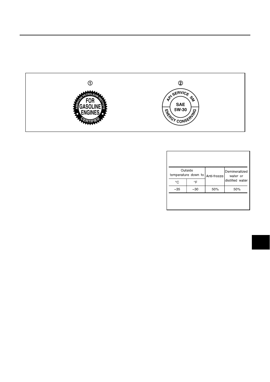
Select only engine oils that meet the American Petroleum Institute (API) certification and International Lubri-
cant Standardization and Approval Committee (ILSAC) certification and SAE viscosity standard. These oils
have the API certification mark on the front of the container. Oils which do not have the specified quality label
should not be used as they could cause engine damage.

Anti-Freeze Coolant Mixture Ratio

NLS0007G

The engine cooling system is filled at the factory with a high-quality,
year-round, anti-freeze coolant solution. The anti-freeze solution
contains rust and corrosion inhibitors. Therefore, additional cooling
system additives are not necessary.

CAUTION:

When adding or replacing coolant, be sure to use only genuine
NISSAN Long Life Antifreeze/ Coolant or equivalent with the
proper mixture ratio of 50% anti-freeze and 50% demineralized
water/distilled water.
Other types of coolant solutions may damage your cooling sys-
tem.

1.

API certification mark

2.

API service symbol

SAIA1514E

SMA947CA

MA-14

ENGINE MAINTENANCE (VQ35DE ENGINE)

ENGINE MAINTENANCE (VQ35DE ENGINE)

PFP:10001

Checking Drive Belts

NLS0009Y

WARNING:

Be sure to perform when engine is stopped.
1.

Inspect belts for cracks, fraying, wear and oil. If necessary, replace.

2.

Inspect drive belt deflection or tension at a point on belt midway
between pulleys.

Inspection should be done only when engine is cold, or over
30 minutes after engine is stopped.

Measure the belt tension with belt tension gauge (Commercial
service tool: BT3373-F or equivalent) at points marked 
shown in the figure.

When measuring the deflection, apply 98 N (10 kg, 22 lb) at
the   marked point.

Adjust if the belt deflection exceeds the limit or if the belt ten-
sion is not within specifications.

CAUTION:

When checking the belt deflection or the tension immediately after installation, first adjust it to
the specified value. Then, after turning crankshaft two turns or more, re-adjust to the specified
value to avoid variation in deflection between pulleys.

Tighten idler pulley lock nut by hand and measure the deflection or the tension without loose-
ness.

Belt Deflection and Tension

*: If belt tension gauge cannot be installed at check points shown, check drive belt tension at different location on belt.

Tension Adjustment

NLS0009Z

1

: Power steering oil pump

2

: Alternator

3

:  Idler  pulley  2

4

: Crankshaft pulley

5

:  Idler  pulley  3

6

: A/C compressor

7

:  Idler  pulley  1

A

: With idler pulley 1

B

: Without idler pulley 1

PBIC5329E

Items

Deflection adjustment

Unit: mm (in)

Tension adjustment*

Unit: N (kg, lb)

Used belt

New belt

Used belt

New belt

Limit

After adjustment

Limit

After adjustment

Alternator and 
power steering 
oil pump belt

With idler pulley 1

7 (0.28)

4 - 5

(0.16 - 0.20)

3.5 - 4.5

(0.138 - 0.177)

294 (30, 66)

730 - 818

(74.5 - 83.4,

164 - 184)

838 - 926

(85.5 - 94.5,

188 - 208)

Without idler pul-
ley 1

12 (0.47)

7 - 8

(0.28 - 0.31)

6 - 7

(0.24 - 0.28)

A/C compressor belt

12 (0.47)

9 - 10

(0.35 - 0.39)

8 - 9

(0.31 - 0.35)

196 (20, 44)

348 - 436

(35.5 - 44.5,

78 - 98)

470 - 559

(48 - 57,

106 - 126)

Applied pushing force

98 N (10 kg, 22 lb)

Portion

Belt tightening method for adjustment

Alternator and power steering oil pump belt

Adjusting bolt on idler pulley

A/C compressor belt

Adjusting bolt on idler pulley

ENGINE MAINTENANCE (VQ35DE ENGINE)

MA-15

C

D

E

F

G

H

I

J

K

M

A

B

MA

CAUTION:

When belt is replaced with a new one, adjust it to value for “New belt” to accommodate for insuffi-
cient adaptability with pulley grooves.

When deflection or tension of belt being used exceeds “Limit”, adjust it to value for “After adjust-
ment”.

When checking belt deflection or tension immediately after installation, first adjust it to the speci-
fied value. Then, after turning crankshaft two turns or more, re-adjust to the specified value to
avoid variation in deflection between pulleys.

When installing belt, make sure that it is correctly engaged with pulley grooves.

Keep engine oil, working fluid and engine coolant away from belt and pulley grooves.

Do not twist or bend belt excessively.

ALTERNATOR AND POWER STEERING OIL PUMP BELT

1.

Remove front engine undercover with power tool.

2.

Loosen idler pulley lock nut (A) and adjust tension by turning
adjusting bolt (B).

For the specified belt tension, refer to 

MA-14, "Checking Drive

Belts"

 .

3.

Tighten nut (A).

A/C COMPRESSOR BELT

1.

Remove front engine undercover with power tool.

2.

Loosen idler pulley lock nut (C) and adjust tension by turning adjusting bolt (D).

For the specified belt tension, refer to 

MA-14, "Checking Drive Belts"

 .

3.

Tighten nut (C).

Changing Engine Coolant

NLS0007J

WARNING:

To avoid being scalded, do not change engine coolant when the engine is hot.

Wrap a thick cloth around radiator cap and carefully remove radiator cap. First, turn radiator cap a
quarter of a turn to release built-up pressure. Then turn radiator cap all the way.

Be careful not to allow engine coolant to contact drive belts.

DRAINING ENGINE COOLANT

1.

Remove engine room cover (RH and LH). Refer to 

EM-15, "ENGINE ROOM COVER"

 . 

2.

Remove air duct (inlet). Refer to 

EM-19, "AIR CLEANER AND AIR DUCT"

 .

3.

Open radiator drain plug at the bottom of radiator, and then remove radiator cap. 

1

: Alternator and power steering oil pump belt

2

: Power steering oil pump 

3

: Alternator

4

: Idler pulley 2

5

: Crankshaft pulley

6

: Idler pulley 3

7

: A/C compressor

8

: A/C compressor belt

9

: Idler pulley 1

E

: With idler pulley 1

F

: Without idler pulley 2


: 34.8 N·m (3.5 kg-m, 26 ft-lb)

PBIC5330E


: 34.8 N·m (3.5 kg-m, 26 ft-lb)

MA-16

ENGINE MAINTENANCE (VQ35DE ENGINE)

When draining all of engine coolant in the system, open water drain plugs on cylinder block. Refer
to 

EM-125, "DISASSEMBLY"

 .

4.

Remove reservoir tank as necessary, and drain engine coolant and clean reservoir tank before installing.

5.

Check drained engine coolant for contaminants such as rust, corrosion or discoloration.
If contaminated, flush the engine cooling system. Refer to 

CO-13, "FLUSHING COOLING SYSTEM"

 .

REFILLING ENGINE COOLANT

1.

Install reservoir tank if removed, and radiator drain plug.

CAUTION:

Be sure to clean drain plug and install with new O-ring.

If water drain plugs on cylinder block are removed, close and tighten them. Refer to 

EM-129,

"ASSEMBLY"

 .

2.

Make sure that each hose clamp has been firmly tightened.

3.

Remove air relief plug on heater hose.

4.

Fill radiator, and reservoir tank if removed, to specified level.

Pour engine coolant through engine coolant filler neck
slowly of less than 2  (2-1/8 US qt, 1-3/4 lmp qt) a minute
to allow air in system to escape.

Use genuine NISSAN Long Life Antifreeze/Coolant or
equivalent mixed with water (distilled or demineralized).
Refer to 

MA-12, "RECOMMENDED FLUIDS AND LUBRI-

CANTS"

 .

1

: Radiator drain plug hole

2

: Front engine under cover

: Engine front

PBIC3395E

Radiator drain plug:             

: 1.2 N·m (0.12 kg-m, 11 in-lb)

SBIA0445E

Engine coolant capacity
(With reservoir tank at “MAX” level)

: Approximately 8.9   (9-3/8 US qt, 7-7/8 lmp qt)

SMA182B


Content   ..  952  953  954  955   ..