Infiniti M35/M45 Y50. Manual - part 934
INTERIOR ROOM LAMP
LT-281
C
D
E
F
G
H
I
J
L
M
A
B
LT
How to Perform Trouble Diagnoses
NKS003T5
1.
Confirm the symptom or customer complaint.
2.
Understand operation description and function description. Refer to
.
3.
Perform the Preliminary Check. Refer to
4.
Check symptom and repair or replace the cause of malfunction.
5.
Does the interior room lamp operate normally? If YES, GO TO 6. If NO, GO TO 4.
6.
INSPECTION END
52
B
Ground
ON
—
Approx. 0 V
55
W
Battery power
supply
OFF
—
Battery voltage
57
SB
Trunk switch
signal
OFF
Trunk room lamp
switch
ON (open)
Approx. 0 V
OFF (close)
Battery voltage
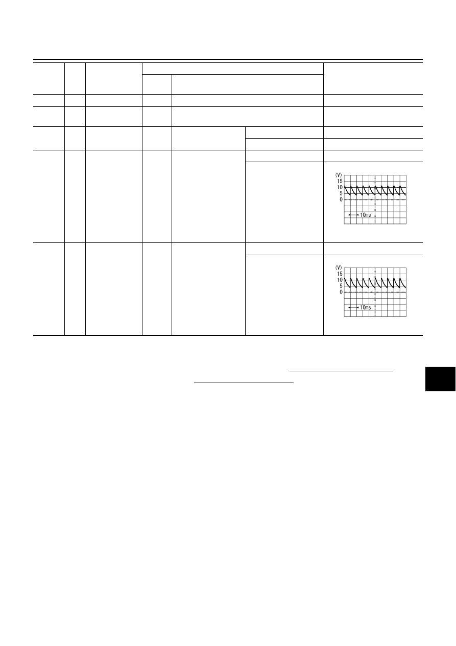
62
V
Front door switch
driver side signal
OFF
Front door switch
driver side
ON (open)
Approx. 0 V
OFF (closed)
Approx. 7.5 - 8.0 V
63
R/G
Rear door switch
LH signal
OFF
Rear door switch LH
ON (open)
Approx. 0 V
OFF (closed)
Approx. 7.5 - 8.0 V
Terminal
No.
Wire
color
Signal name
Measuring condition
Reference value
Ignition
switch
Operation or condition
PKIB4960J
PKIB4960J