Infiniti M35/M45 Y50. Manual - part 904
ACTIVE AFS
LT-161
C
D
E
F
G
H
I
J
L
M
A
B
LT
DTC B2503 SWIVEL ACTUATOR RH
NKS003QO
1.
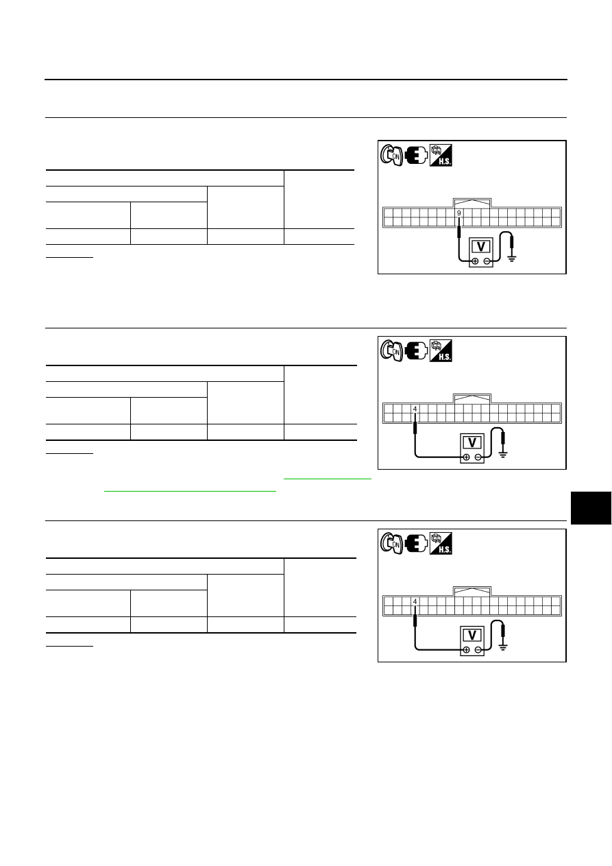
CHECK SWIVEL POSITION SENSOR SIGNAL
1.
Turn ignition switch ON.
2.
Check voltage between AFS control unit harness connector and
ground.
OK or NG
OK
>> GO TO 2.
NG
>>
●
If voltage is less than approx. 0.25V, GO TO 3.
●
If voltage is more than approx. 4.75V, GO TO 6.
2.
CHECK SWIVEL POSITION SENSOR POWER SUPPLY
Check voltage between AFS control unit harness connector and
ground.
OK or NG
OK
>> GO TO 12.
NG
>> Replace AFS control unit. Refer to
and Installation of AFS Control Unit"
3.
CHECK SWIVEL POSITION SENSOR POWER SUPPLY
Check voltage between AFS control unit harness connector and
ground.
OK or NG
OK
>> GO TO 4.
NG
>> GO TO 8.
Terminals
Voltage
(Approx.)
(+)
(-)
AFS control unit
connector
Terminal
F110
9
Ground
0.25 - 4.75 V
PKIC0646E
Terminals
Voltage
(Approx.)
(+)
(-)
AFS control unit
connector
Terminal
F110
4
Ground
4.0 - 6.0 V
PKIC0645E
Terminals
Voltage
(Approx.)
(+)
(-)
AFS control unit
connector
Terminal
F110
4
Ground
4.0 - 6.0 V
PKIC0645E