Infiniti M35/M45 Y50. Manual - part 901
ACTIVE AFS
LT-149
C
D
E
F
G
H
I
J
L
M
A
B
LT
Terminals and Reference Values for AFS Control Unit
NKS003QJ
Ter-
minal
No.
Wire
color
Item
Measuring condition
Reference value
Ignition
switch
Operation or condition
1
B/R
IGN power supply
ON
—
Battery voltage
2
W/R
Swivel position sensor ground
(right)
ON
—
Approx. 0 V
3
GR
AFS switch signal
ON
AFS switch
ON
Approx. 0 V
OFF
Battery voltage
4
Y
Swivel position sensor power
supply (right)
ON
—
Approx. 5 V
6
V/W
Height sensor power supply
ON
—
Approx. 5 V
7
P
CAN-L
—
—
—
8
B/R
Height sensor ground
ON
—
Approx. 0 V
9
W/B
Swivel position sensor signal
(right)
ON
Low beam headlamp
(right) swivel angle
0
°
Approx. 1.5 V
Maximum
angle
Approx. 2.5 V
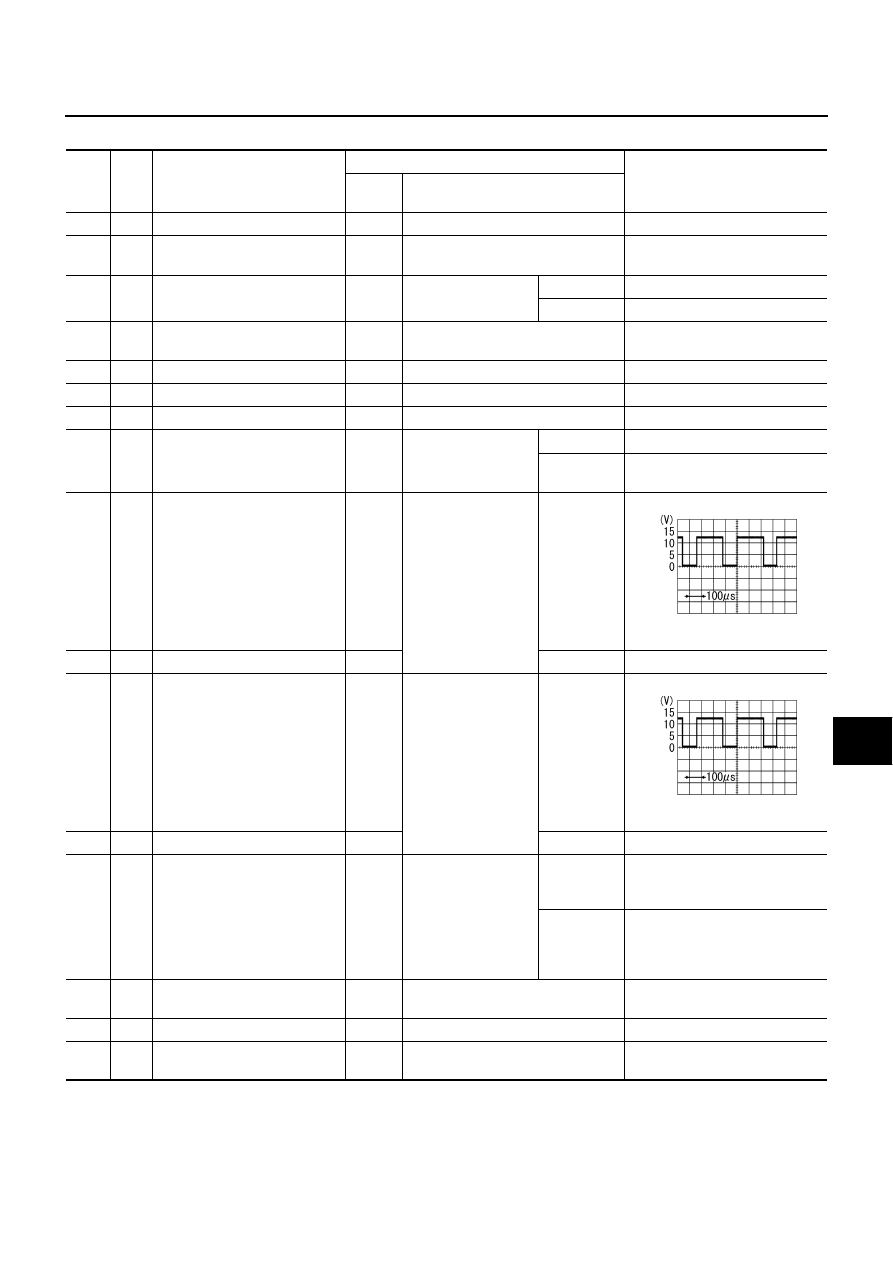
11
R
Swivel motor 1 phase
−
(right)
ON
Low beam headlamp
(right) swivel
ON
Reference waveform
Approx. 8 - 12 V
13
B
Swivel motor 2 phase
−
(right)
ON
OFF
Approx. 9.5 - 11.5 V
15
BR/L
Swivel motor 1 phase+ (left)
ON
Low beam headlamp
(left) swivel
ON
Reference waveform
Approx. 8 - 12 V
17
Y/G
Swivel motor 2 phase+ (left)
ON
OFF
Approx. 9.5 - 11.5 V
19
V
Aiming motor drive signal (right)
ON
Low beam headlamp
(right) auto aiming
Unloaded
vehicle posi-
tion
Approx. 9 V
Maximum
laden condi-
tion
Approx. 4.8 V
(With 18- inch wheel)
Approx. 5.2 V
(With 19 -inch wheel)
24
V/R
Swivel position sensor power
supply (left)
ON
—
Approx. 5 V
25
B
Ground
ON
—
Approx. 0 V
27
R/W
Swivel position sensor ground
(left)
ON
—
Approx. 0 V
SKIB2408J
SKIB2408J