Infiniti M35/M45 Y50. Manual - part 898


  Index      Infiniti     Infiniti M35/M45 Y50 - service repair manual 2007 year


Search            copyright infringement  


Content   ..  896  897  898  899   ..


Infiniti M35/M45 Y50. Manual - part 898


ACTIVE AFS

LT-137

C

D

E

F

G

H

I

J

L

M

A

B

LT

AFS OPERATION
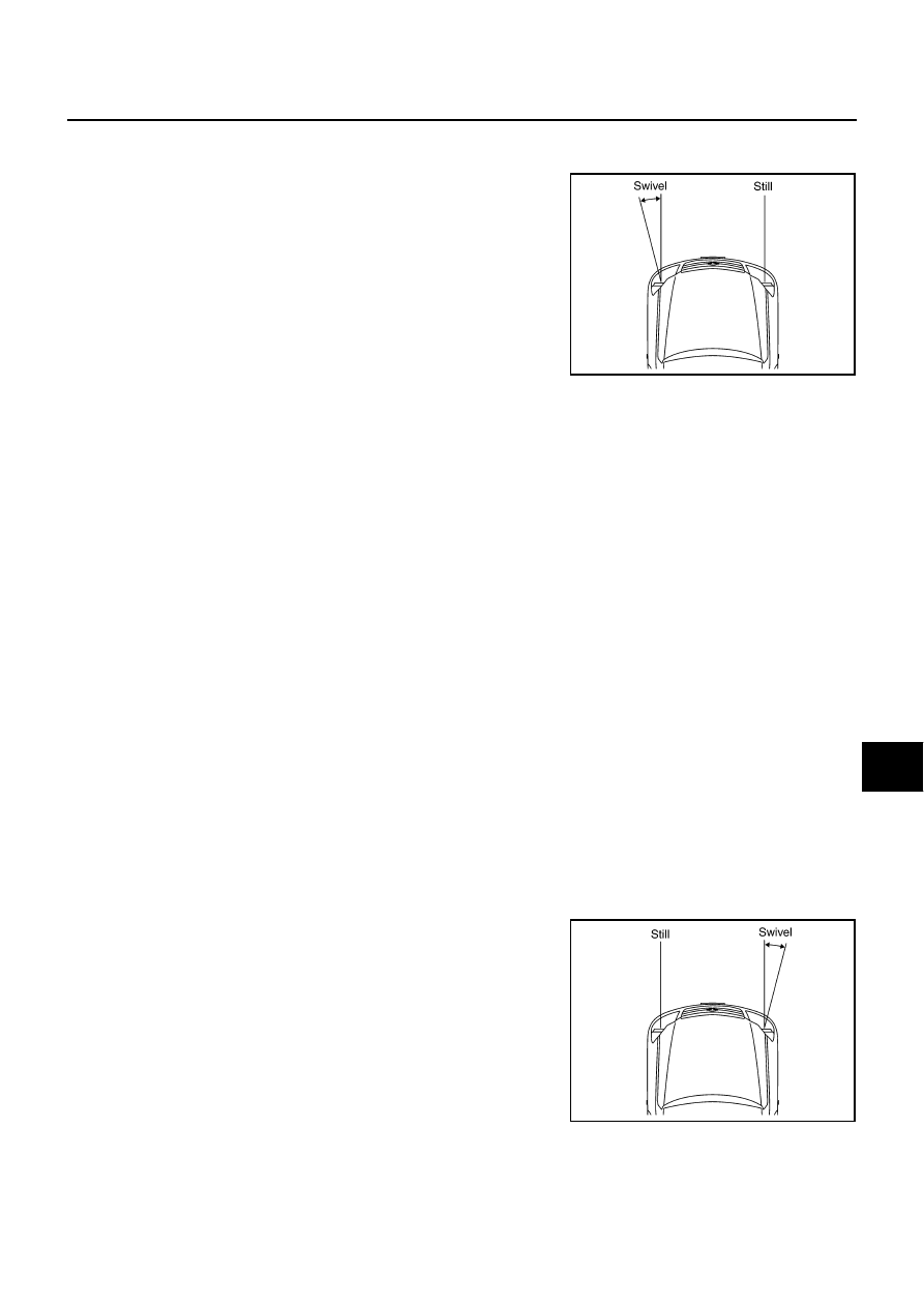
When The Steering Wheel Is Turned To The Left

Swivel motor driving signal (1-phase) is transmitted when the steer-
ing wheel is turned to left approximately more than 10*  degrees
(predetermined), with vehicle speed at approximately 25 km/h (15.5
MPH) or more, headlamps (HIGH/LOW) illuminated, AFS switch ON
and the engine running and the A/T select lever in any position
except range P or R. 
* : Slightly different from the case when it is turned to the right.
Swivel motor driving signal (1-phase) is sent

to front combination lamp LH terminal 17

through AFS control unit terminal 15,

to AFS control unit terminal 38

through front combination lamp LH terminal 21.

And swivel motor driving signal (2-phase) is sent:

to front combination lamp LH terminal 16

through AFS control unit terminal 17,

to AFS control unit terminal 36

through front combination lamp LH terminal 20.

Swivel position sensor detects swivel angle during ignition switch ON, and transmits swivel position sensor
signals to the AFS control unit:
When ignition switch is turn to ON position, power is supplied

to front combination lamp LH terminal 15

through AFS control unit terminal 24.

When ignition switch is turn to ON position, swivel position sensor signal input is supplied

to AFS control unit terminal 29

through front combination lamp LH terminal 14.

Ground is supplied

to front combination lamp LH terminal 19

through AFS control unit terminal 27.

The low beam headlamp LH starts to swivel to the left.
The swivel motor driving signals are blocked and the swivel motion stops when the steering angle reaches
approximately more than 80 degrees (predetermined). The low beam headlamp will not swivel any further no
matter how further left. As the steering wheel is turned back to the right, the swivel motor driving signals (both
1-phase and 2-phase) will be reversed, causing low beam headlamp LH to start swiveling to the right. When
steering angle becomes smaller than predetermined value, the low beam headlamp is set in the straight-
ahead position, swivel motor driving signals are blocked and low beam headlamps stop swiveling.

When The Steering Wheel Is Turned To The Right

Swivel motor driving signal (1-phase) is transmitted when the steer-
ing wheel is turned to right approximately more than 10*  degrees
(predetermined), with headlamps (HIGH/LOW) illuminated, AFS
switch ON, the engine running and the A/T select lever in any posi-
tion except range P or R. 
* : Slightly different from the case when it is turned to the left.
Swivel motor driving signal (1-phase) is sent

to front combination lamp RH terminal 16

through AFS control unit terminal 34,

to AFS control unit terminal 11

through front combination lamp RH terminal 20.

And swivel motor driving signal (2-phase) is sent

to front combination lamp RH terminal 17

through AFS control unit terminal 32,

to AFS control unit terminal 13

SKIB4705E

SKIB4706E

LT-138

ACTIVE AFS

through front combination lamp RH terminal 21.

Swivel position sensor detects swivel angle during ignition switch ON, and transmits swivel position sensor
signals to the AFS control unit:
When ignition switch is turn to ON position, power is supplied

to front combination lamp RH terminal 15

through AFS control unit terminal 4.

When ignition switch is turn to ON position, swivel position sensor input signal is supplied

to AFS control unit terminal 9

through front combination lamp RH terminal 14.

Ground is supplied

to front combination lamp RH terminal 19

through AFS control unit terminal 2.

The low beam headlamp RH starts to swivel to the right.
The swivel motor driving signals are blocked and the swivel motion stops when the steering angle reaches
approximately more than 80 degrees (predetermined). The low beam headlamp will not swivel any further no
matter how further right. As the steering wheel is turned back to the left, the swivel motor driving signals (both
1-phase and 2-phase) will be reversed, causing low beam headlamp RH to start swiveling to the left. When
steering angle becomes smaller than predetermined value, the low beam headlamp is set in the straight-
ahead position, swivel motor driving signals are blocked and low beam headlamps stop swiveling.

AFS OFF INDICATOR OPERATION

In response to the state of control, AFS control unit switches com-
mands of AFS off indicator signal sent to unified meter and A/C amp.
via CAN communication; and then turns on/off or blinks AFS off indi-
cator lamp built in the combination meter depending on the following
condition.

Bulb check operation
AFS off indicator lamp is turned off after illuminating for one sec-
ond as a bulb check for AFS off indicator lamp when turn ignition
switch ON is detected.

NOTE:
AFS off indicator lamp is turned off without a lapse of one sec-
ond when start of the engine is detected.

AFS switch operation
AFS off indicator lamp is illuminated while AFS switch is OFF.
AFS off indicator lamp is turned off while AFS switch is ON.

System warning operation
AFS off indicator lamp illuminates at intervals of approximately one second when AFS control unit detects
any specific DTC (diagnosis trouble code), or when unified meter and A/C amp. cannot receive AFS off
indicator signals.

NOTE:
Unified meter and A/C amp. transmits a command to combination meter to blink AFS off indicator lamp
when they cannot receive AFS off indicator signal.

SWIVEL ACTUATOR INITIALIZATION

AFS control unit performs swivel operation to initialize swivel actuator when start of the engine is detected.
Straight-ahead position of low beam headlamps is adjusted by turning low beam headlamps to outside vehicle
with specified swivel angle after turning it to the center of vehicle and making sure that it reaches the stopper. 
Swivel actuator initialization shall be performed every time when start of the engine is detected.

SKIB4765E

ACTIVE AFS

LT-139

C

D

E

F

G

H

I

J

L

M

A

B

LT

HEADLAMP AUTO AIMING OPERATION 

The height sensor detects a change in height of rear vehicle with ignition switch ON, and transmits signals to
the AFS control unit:
When ignition switch is turn to ON position, power is supplied

to height sensor terminal 1

through AFS control unit terminal 6. 

When ignition switch is turned to ON position, height sensor input signal is supplied

to AFS control unit terminal 28

through height sensor terminal 2.

Ground is supplied

to height sensor terminal 3

through AFS control unit terminal 8.

Aiming motor driving signal (voltage signal that corresponds to the vehicle height) is transmitted depending on
the height sensor signal at the start of the engine

to front combination lamp LH terminal 12

through AFS control unit terminal 40,

to front combination lamp RH terminal 12

through AFS control unit terminal 19.

Output of aiming motor driving signal is maintained unless headlamp (HIGH/LOW) illuminate detected.
Auto aiming control operation starts when headlamps (HIGH/LOW) illuminate detected.
When headlamps (HIGH/LOW) illuminate, output of aiming motor driving signal is changed according to the
height sensor signal. After the change, it is changed according to height sensor signals with predetermined
timing based on driving condition while headlamps are ON.

Auto Aiming Operation

AFS control unit starts outputting aiming motor drive signal when the engine starts, and continues to output it
until the engine stops. Aiming motor drive signal changes output when the specified conditions described
below are met.
Headlamp aiming motors set the low beam projectors according to aiming motor drive signals received from
AFS control unit, both headlamp aiming motors cause the low beam projectors to move to the position com-
manded by the signal.
The aiming motor drive signal level retains when the following conditions are not met. 

AFS control unit operation when the vehicle is stopped (low beam headlamps illuminated)
Headlamp aiming motor drive signal is changed when vehicle height is stabilized with a parked condition,
depending on the height sensor signal detected with height sensor signal by AFS control unit.

AFS control unit operation when the vehicle is running (low beam headlamps illuminated)
When vehicle is running, headlamp aiming motor drive signal is changed depending on the height sensor
signal which is detected when AFS control unit detects constant steady speed of vehicle.
When the vehicle is accelerating or decelerating, AFS control unit keeps headlamp aiming motor drive sig-
nal voltage level rather than changing it, so that the low beam projectors of both headlamps do not oper-
ate.

CAN COMMUNICATION SYSTEM DESCRIPTION

CAN (Controller Area Network) is a serial communication line for real time application. It is an on-vehicle mul-
tiplex communication line with high data communication speed and excellent error detection ability. Many elec-
tronic control units are equipped onto a vehicle, and each control unit shares information and links with other
control units during operation (not independent). In CAN communication, control units are connected with 2
communication lines (CAN H line, CAN L line) allowing a high rate of information transmission with less wiring.
Each control unit transmits/receives data but selectively reads required data only.

CAN COMMUNICATION UNIT

Refer to 

LAN-50, "CAN System Specification Chart"

 .

LT-140

ACTIVE AFS

Component Parts Description

NKS003QG

AFS CONTROL UNIT

AFS control unit determines current vehicle conditions by received signals and controls AFS and headlamp
auto aiming.

SWIVEL ACTUATOR

Swivel actuator is configured with swivel motor and swivel position
sensor and is built in headlamps.

Swivel motor (step motor)
Swivel motor is a two

phase step motor. It is driven according to drive signals from AFS control unit when

two drive windings are energized in set sequences, and adjusts low beam projector of headlamp.
The direction of actuator rotation can be changed as desired by selecting appropriate energizing
sequences.

Swivel position sensor
Swivel position sensor detects swivel angle and transmits a swivel position sensor signal to the AFS con-
trol unit.

AIMING MOTOR

Aiming motor is installed outside the headlamps. Headlamp aiming
motors set the low beam projectors according to headlamp aiming
motor drive signals received from AFS control unit.

SKIB4688E

SKIB4690E

SKIB4688E


Content   ..  896  897  898  899   ..