Infiniti M35/M45 Y50. Manual - part 850


  Index      Infiniti     Infiniti M35/M45 Y50 - service repair manual 2007 year


Search            copyright infringement  


Content   ..  848  849  850  851   ..


Infiniti M35/M45 Y50. Manual - part 850


TROUBLE DIAGNOSIS

LAN-49

[CAN]

C

D

E

F

G

H

I

J

L

M

A

B

LAN

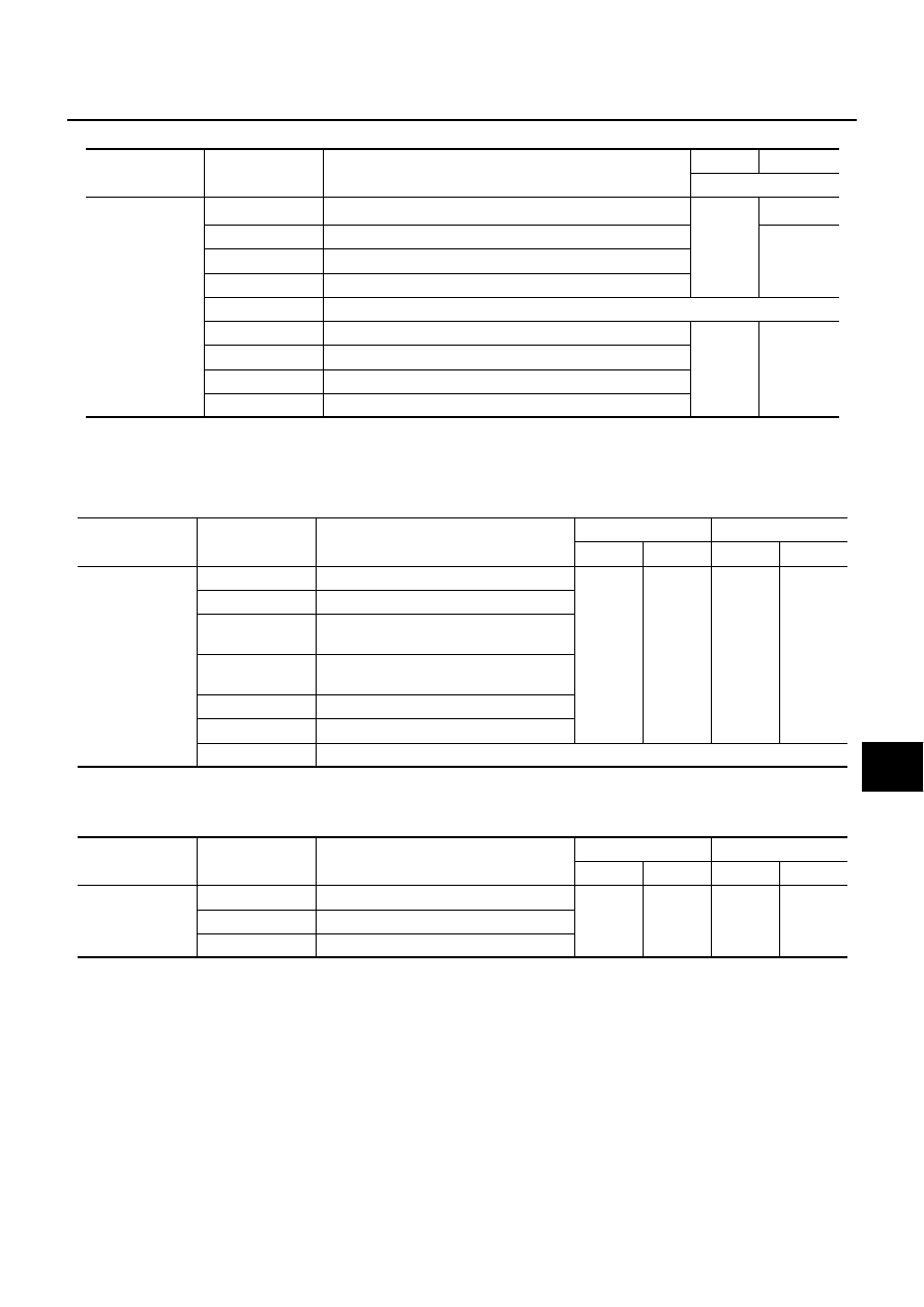
ABS actuator and electric unit (control unit)

CAUTION:

Never replace the unit even when “NG” is indicated on the “INITIAL DIAG” at this stage. Follow the trouble diagnosis proce-
dures. 

ICC sensor integrated unit

0: Error at present, 1 – 39: Error in the past (Number means the number of times the ignition switch is turned OFF

ON)

*: 39 or higher number is fixed at 39 until the self-diagnosis result is erased.

IPDM E/R

0: Error at present, 1 – 39: Error in the past (Number means the number of times the ignition switch is turned OFF

ON)

*: 39 or higher number is fixed at 39 until the self-diagnosis result is erased.

SELECT SYS-

TEM

CAN DIAG SUP-

PORT MNTR

Description

Normal

Error

PRSNT

ABS

INITIAL DIAG

Status of CAN controller

OK

NG

Caution

TRANSMIT DIAG

Signal transmission status

UNKWN

ECM

Signal receiving status from the ECM

TCM

Signal receiving status from the TCM

METER/M&A

Not used even though indicated

STRG

Signal receiving status from the steering angle sensor

OK

UNKWN

ICC

Signal receiving status from the ICC sensor integrated unit

AWD/4WD

Signal receiving status from the AWD control unit

RAS C/U

Signal receiving status from the RAS control unit

SELECT SYS-

TEM

CAN DIAG SUP-

PORT MNTR

Description

Normal

Error

PRSNT

PAST

PRSNT

PAST

ICC

TRANSMIT DIAG

Signal transmission status

OK

OK

or

1 – 39

*

UNKWN

0

ECM

Signal receiving status from the ECM

VDC/TCS/ABS

Signal receiving status from the ABS actu-
ator and electric unit (control unit)

METER/M&A

Signal receiving status from the unified 
meter and A/C amp.

BCM/SEC

Signal receiving status from the BCM

TCM

Signal receiving status from the TCM

STRG

Not used even though indicated

SELECT SYS-

TEM

CAN DIAG SUP-

PORT MNTR

Description

Normal

Error

PRSNT

PAST

PRSNT

PAST

IPDM E/R

TRANSMIT DIAG

Signal transmission status

OK

OK

or

1 – 39

*

UNKWN

0

ECM

Signal receiving status from the ECM

BCM/SEC

Signal receiving status from the BCM

LAN-50

[CAN]

TROUBLE DIAGNOSIS

CAN System Specification Chart

NKS004FU

Determine CAN system type from the following specification chart. Then choose the correct diagnosis sheet.

NOTE:
Refer to 

LAN-19, "CHECK OF CAN SYSTEM TYPE (HOW TO USE CAN SYSTEM TYPE SPECIFICATION

CHART)"

  for how to use CAN system specification chart.

×

: Applicable

Body type

Sedan

Axle

2WD

AWD

Engine

VQ35DE/VK45DE

VQ35DE

Transmission

A/T

Brake control

VDC

Adaptive front-lighting system

×

×

×

×

×

×

×

×

Lane departure warning

×

×

×

Navigation system

×

×

×

×

×

×

Rear active steer

×

×

×

ICC system

×

×

×

CAN  system  type

1

2

3

4

5

6

7

8

9

10

11

Diagnosis sheet

LAN-

70

LAN-

71

LAN-

72

LAN-

73

LAN-

74

LAN-

75

LAN-

76

LAN-

77

LAN-

78

LAN-

79

LAN-

80

CAN communication signal chart

LAN-52, "TYPE 1/TYPE 2/TYPE 3/TYPE 4/TYPE 5/TYPE 

6/TYPE 7"

LAN-55, "TYPE 8/TYPE 9/TYPE 

10/TYPE 11"

TROUBLE DIAGNOSIS

LAN-51

[CAN]

C

D

E

F

G

H

I

J

L

M

A

B

LAN

VEHICLE EQUIPMENT IDENTIFICATION INFORMATION

NOTE:
Check CAN system type from the vehicle shape and equipment.

PKID0330E

LAN-52

[CAN]

TROUBLE DIAGNOSIS

CAN Communication Signal Chart

NKS004FV

Refer to 

LAN-15, "How to Use CAN Communication Signal Chart"

  for how to use CAN communication signal

chart.

TYPE 1/TYPE 2/TYPE 3/TYPE 4/TYPE 5/TYPE 6/TYPE 7

NOTE:
Refer to 

LAN-41, "Abbreviation List"

  for the abbreviations of the connecting units. 

T: Transmit

R: Receive

Signals

ECM

AF

S

*1

BCM

LAN

E

*2

TCM

AV

I-

KEY

M&

A

STRG

TPM

S

RAS

*3

PSB

ADP

ABS

ICC

*4

IPDM-

E

A/C compressor request signal

T

R

Accelerator pedal position signal 

T

R

R

R

ASCD CRUISE lamp signal

T

R

ASCD OD cancel request signal

T

R

ASCD operation signal

T

R

ASCD SET lamp signal

T

R

Battery voltage signal

T

Closed throttle position signal

T

R

Cooling fan speed request signal

T

R

Engine coolant temperature signal

T

R

Engine speed signal

T

R

R

R

R

R

R

Engine status signal

T

R

R

R

Fuel consumption monitor signal

T

R

R

ICC brake switch signal

T

R

ICC prohibition signal

T

R

ICC steering switch signal

T

R

Malfunctioning indicator lamp signal

T

R

Power generation command value signal

T

R

Stop lamp switch signal

T

R

R

T

T

R

Wide open throttle position signal

T

AFS OFF indicator signal

T

R

A/C switch signal

R

T

ACC signal

T

R

R

Blower fan motor switch signal

R

T

Buzzer output signal

T

R

T

R

R

T

Day time running light request signal

T

R

Door lock/unlock status signal

T

R

Door switch signal

T

R

R

R

R

R

Door unlock signal

T

R

Front fog light request signal

T

R

R

Front wiper request signal

T

R

R

High beam request signal

T

R

R


Content   ..  848  849  850  851   ..