Infiniti M35/M45 Y50. Manual - part 846


  Index      Infiniti     Infiniti M35/M45 Y50 - service repair manual 2007 year


Search            copyright infringement  


Content   ..  844  845  846  847   ..


Infiniti M35/M45 Y50. Manual - part 846


TROUBLE DIAGNOSES WORK FLOW

LAN-33

[CAN FUNDAMENTAL]

C

D

E

F

G

H

I

J

L

M

A

B

LAN

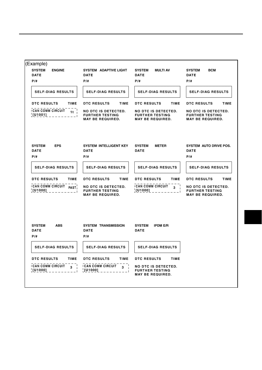
Past Error — Open Circuit —

Review CAN communication signal chart based on information received from the interview with the customer
and on past error information from SELF-DIAG RESULTS and CAN DIAG SUPPORT MNTR.
1.

SELF-DIAG RESULTS: Inspect the control units indicating “U1000” or “U1001” on SELF-DIAG RESULTS.

SKIB8731E

LAN-34

[CAN FUNDAMENTAL]

TROUBLE DIAGNOSES WORK FLOW

2.

CAN DIAG SUPPORT MNTR (with PAST): Check the CAN DIAG SUPPORT MNTR (with PAST) of units
indicating “U1000” or “U1001” on SELF-DIAG RESULTS. Draw a line on the diagnosis sheet to indicate
the possible error circuit.

NOTE:
For the details of each indication on CAN DIAG SUPPORT MNTR, refer to 

LAN-44, "CAN Diagnostic Sup-

port Monitor"

 .

a.

Reception item of “ENGINE”: “VDC/TCS/ABS”, “3” is indicated in the “PAST”. This means ECM could not
receive the signal from ABS in the past. Draw a line between ECM and ABS (line 2-a in the figure).

b.

Reception item of “METER”: “VDC/TCS/ABS”, “3” is indicated in the “PAST”. This means M&A could not
receive the signal from ABS in the past. Draw a line between M&A and ABS (line 2-b in the figure).

c.

Reception item of “TRANSMISSION”: “VDC/TCS/ABS”, “3” is indicated in the “PAST”. This means TCM
could not receive the signal from ABS in the past. Draw a line between TCM and ABS (line 2-c in the fig-
ure).

SKIB8732E

TROUBLE DIAGNOSES WORK FLOW

LAN-35

[CAN FUNDAMENTAL]

C

D

E

F

G

H

I

J

L

M

A

B

LAN

3.

CAN DIAG SUPPORT MNTR (without PAST): Check the CAN DIAG SUPPORT MNTR (without PAST) of
units indicating “U1000” or “U1001” on SELF-DIAG RESULTS. Draw a line on the diagnosis sheet to indi-
cate the possible error circuit.

NOTE:

While an error occurred in the past according to SELF-DIAG RESULTS, it is unclear which signal is not
received. Assume that errors were detected from all reception items.

Draw a single line among the unit and all reception items. (Work flow differs from CAN DIAG SUPPORT
MNTR (with PAST).)

a.

Reception item of “EPS”: Assume that the unit could not receive the signals from ECM, ABS, and M&A.
Draw a line among EPS, ECM, ABS, and M&A (line 3-a in the figure).

b.

Reception item of “ABS”: Assume that the unit could not receive the signal from ECM. Draw a line
between ABS and ECM (line 3-b in the figure).

SKIB8733E

LAN-36

[CAN FUNDAMENTAL]

TROUBLE DIAGNOSES WORK FLOW

4.

Search for the possible cause using CAN communication signal chart using information from the interview
with the customer.

NOTE:
For the details of CAN communication signal, refer to 

LAN-52, "CAN Communication Signal Chart"

 .

a.

ABS warning lamp turned ON and speedometer did not move: This means that “ABS warning lamp signal”
and “Vehicle speed signal” could not communicate between M&A and ABS (4-a in the figure).

b.

The tachometer moved normally: This means that “Engine speed signal” could communicate normally
between ECM and M&A (4-b in the figure).

SKIB8895E


Content   ..  844  845  846  847   ..