Infiniti M35/M45 Y50. Manual - part 808


  Index      Infiniti     Infiniti M35/M45 Y50 - service repair manual 2007 year


Search            copyright infringement  


Content   ..  806  807  808  809   ..


Infiniti M35/M45 Y50. Manual - part 808


POWER WINDOW SYSTEM

GW-29

C

D

E

F

G

H

J

K

L

M

A

B

GW

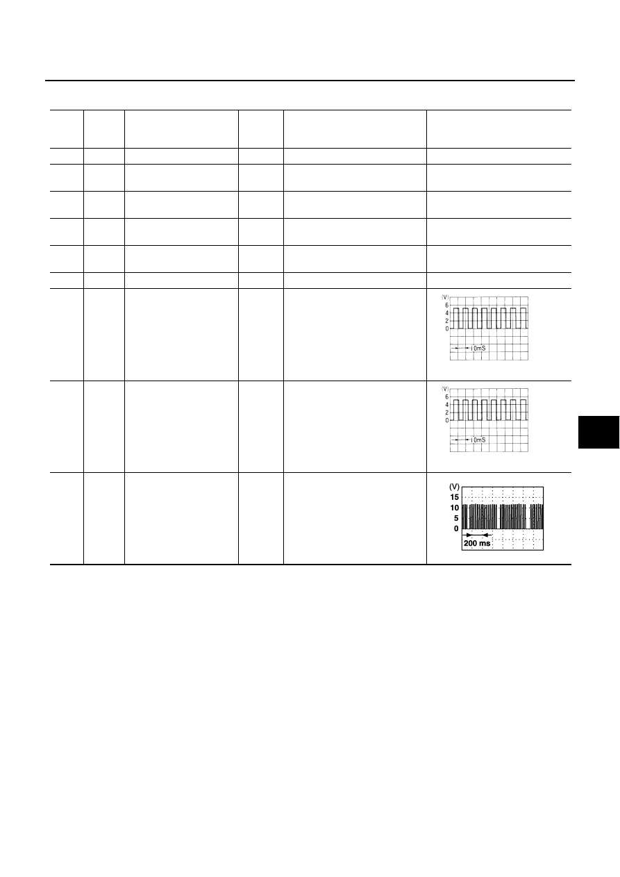
Terminal and Reference Value for (Front and Rear) Power Window Sub-Switch

NIS0021N

 (): Power window sub-switch (rear LH or RH)

Termi-

nal

Wire 

color

Item

Signal

Input/

Output

Condition

Voltage [V]

(Approx.)

3

W/B

Encoder ground

0

4

G/R

Encoder power supply

Output

When ignition switch ON or power 
window timer operates

10

8

L

(G)

Power window motor
UP signal

Output

When power window motor is
UP at operated.

 Battery voltage

9

G

(L)

Power window motor 
DOWN signal

Output

When power window motor is
DOWN at operated.

Battery voltage

10

W/B

(W/R)

Battery power supply

Input

Battery voltage

11

B

Ground

0

12

G/Y

Encoder pulse signal 1

Input

When power window motor oper-
ates.

15

G/W

Encoder pulse signal 2

Input

When power window motor oper-
ates.

16

Y

Power window serial link

Input/

Output

IGN SW ON or power window 
timer operating.

OCC3383D

OCC3383D

PIIA2344J

GW-30

POWER WINDOW SYSTEM

CONSULT-II Function (BCM)

NIS0021O

CONSULT-II can display each diagnostic item using the diagnostic test modes shown following.

CONSULT-II START PROCEDURE

Refer to 

GI-38, "CONSULT-II Start Procedure"

WORK SUPPORT

DATE MONITOR

Work Flow

NIS0021P

1.

Check the symptom and customer's requests.

2.

Understand the outline of system. Refer to 

GW-14, "System Description"

3.

According to the trouble diagnosis chart, repair or replace the cause of the malfunction.
Refer to 

GW-30, "Trouble Diagnosis Symptom Chart"

4.

Does power window system operate normally? Yes, GO TO 5, If No, GO TO 3.

5.

INSPECTION END

Trouble Diagnosis Symptom Chart

NIS0021Q

Make sure other systems using the signal of the following systems operate normally.

BCM diagnostic test item

Check item diagnostic test mode

Content

RETAINED PWR

Work support

Changes setting of each function.

Data monitor

Displays the input data of BCM in real time.

Work item

Description

RETAINED PWR

Rap signal’s power supply period can be changed by mode setting. Selects rap signal’s power 
supply period between three steps

MODE1 (45 sec.) / MODE2 (OFF) / MODE 3 (2 min.).

Work item

Description

IGN ON SW

Indicates (ON / OFF) condition of ignition switch

DOOR SW–DR

Indicates (ON / OFF) condition of front door switch driver side 

DOOR SW–AS

Indicates (ON / OFF) condition of front door switch passenger side

Symptom

Repair order

Refer to page

None of the power windows can be operated using any switch.

1.

Check BCM power supply and ground circuit 

GW-32

2.

Check power window main switch power sup-
ply and ground circuit 

GW-33

3.

Check power window serial link 

GW-54

Driver side power window alone does not operate.

1.

Check power window motor (front driver side) 
circuit 

GW-36

2.

Replace power window main switch

Front passenger side power window alone does not operate.

1.

Check power window main switch power sup-
ply and ground circuit check

GW-33

2.

Check power window sub-switch (front passen-
ger side) power and ground circuit 

GW-34

3.

Check power window serial link 

GW-54

4.

Check power window motor (front passenger 
side) circuit 

GW-37

5.

Replace BCM

BCS-15

POWER WINDOW SYSTEM

GW-31

C

D

E

F

G

H

J

K

L

M

A

B

GW

Rear LH or RH side power window alone does not operate

1.

Check power window sub-switch 
(rear LH or RH) 
power and ground circuit 

GW-35

2.

Check power window serial link (rear LH or RH)

GW-56

3.

Check power window motor (rear LH or RH) cir-
cuit 

GW-38

4.

Replace rear power window switch (LH or RH)

Anti-pinch system does not operate normally (driver side)

1.

Initialization

GW-63

2.

Door window sliding part malfunction

A foreign material adheres to window glass 
or glass run rubber.

Glass run rubber wear or deformation.

Sash is tilted too much, or no enough.

3.

Encoder circuit check (driver side)

GW-40

Anti-pinch system does not operate normally (passenger side)

1.

Initialization

GW-63

2.

Door window sliding part malfunction

A foreign material adheres to window glass 
or glass run rubber.

Glass run rubber wear or deformation.

Sash is tilted too much, or no enough.

3.

Encoder circuit check (passenger side)

GW-43

Anti-pinch system does not operate normally (rear LH or RH)

1.

Initialization

GW-68

2.

Door window sliding part malfunction

A foreign material adheres to window glass 
or glass run rubber.

Glass run rubber wear or deformation.

Sash is tilted too much, or no enough.

3.

Encoder circuit check (rear LH or RH)

GW-46

Power window retained power operation does not operate 
properly

1.

Check the retained power operation mode set-
ting.

GW-30

2.

Check door switch 

GW-50

3.

Replace BCM.

BCS-15

Does not operate by key cylinder switch

1.

Initialization

GW-63

2.

Check door key cylinder switch 

GW-52

3.

Replace power window main switch

Power window lock switch does not function

Check power window lock switch 

GW-56

Auto operation does not operate but manual operate normally 
(driver side)

1.

Initialization

GW-63

2.

Check encoder circuit (driver side)

GW-40

3.

Replace power window main switch

Auto operation does not operate but manual operate normally 
(passenger side)

1.

Initialization

GW-63

2.

Encoder circuit check (passenger side)

GW-43

3.

Replace front power window switch (passenger 
side)

Auto operation does not operate but manual operate normally 
(rear LH or RH)

1.

Initialization

GW-68

2.

Check encoder circuit (rear LH or RH)

GW-46

3.

Replace rear power window switch (LH or RH)

Symptom

Repair order

Refer to page

GW-32

POWER WINDOW SYSTEM

Check BCM Power Supply and Ground Circuit

NIS0021R

1. 

CHECK FUSE

Check 15A fuse [No. 1, located in fuse block (J/B)]

Check 10A fuse [No. 21, located in fuse block (J/B)]

Check 50A fusible link (letter F , located in the fuse and fusible link box).

NOTE:
Refer to 

GW-14, "Component Parts and Harness Connector Location"

 .

OK or NG

OK

>> GO TO 2.

NG

>> If fuse is blown out, be sure to eliminate cause of malfunction before installing new fuse. Refer to

PG-3, "POWER SUPPLY ROUTING CIRCUIT"

 .

2. 

CHECK POWER SUPPLY CIRCUIT

Check voltage between BCM connector and ground.

OK or NG

OK

>> GO TO 3.

NG

>> Check BCM power supply circuit for open or short.

3. 

CHECK GROUND CIRCUIT

1.

Turn ignition switch OFF.

2.

Disconnect BCM connector.

3.

Check continuity between BCM connector and ground.

OK or NG

OK

>> Power supply and ground circuit are OK.

NG

>> Check BCM ground circuit for open or short.

Terminals

Condition of 

ignition switch

Voltage (V)

(Approx.)

(+)

(–)

BCM connector

Terminal 

M1

38

Ground

ON

Battery voltage

M2

42

OFF

55

PIIB5934E

BCM connector

Terminal

Ground

Continuity 

M2

52

Yes

PIIB5935E


Content   ..  806  807  808  809   ..