Infiniti M35/M45 Y50. Manual - part 769


  Index      Infiniti     Infiniti M35/M45 Y50 - service repair manual 2007 year


Search            copyright infringement  


Content   ..  767  768  769  770   ..


Infiniti M35/M45 Y50. Manual - part 769


FRONT FINAL DRIVE ASSEMBLY

FFD-23

C

E

F

G

H

I

J

K

L

M

A

B

FFD

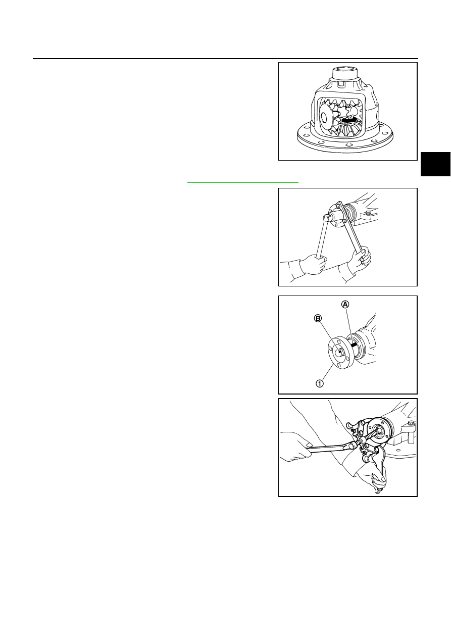
19. Turn pinion mate gear, then remove pinion mate gears, pinion

mate thrust washers, side gears and side gear thrust washers
from differential case.

Drive Pinion Assembly

1.

Remove differential assembly. Refer to 

FFD-20, "Differential Assembly"

 .

2.

Remove drive pinion lock nut with a flange wrench.

3.

Put matching mark (B) on the end of drive pinion. The matching
mark should be in line with the matching mark (A) on companion
flange (1).

CAUTION:

For matching mark, use paint. Do not damage companion
flange and drive pinion.

NOTE:
The matching mark (A) on the final drive companion flange (1)
indicates the maximum vertical runout position.
When replacing companion flange, matching mark is not neces-
sary.

4.

Remove companion flange using the suitable puller.

SDIA0032J

PDIA0798J

PDIA0799J

SDIA1132E

FFD-24

FRONT FINAL DRIVE ASSEMBLY

5.

Press drive pinion assembly out of gear carrier.

CAUTION:

Do not drop drive pinion assembly.

6.

Remove front oil seal.

7.

Remove pinion front bearing inner race.

8.

Remove drive pinion bearing adjusting washer and drive pinion
adjusting washer.

9.

Remove pinion rear bearing inner race and pinion height adjust-
ing washer with replacer.

10. Tap pinion front/rear bearing outer races uniformly a brass rod or

equivalent to removed.

CAUTION:

Be careful not to damage gear carrier.

INSPECTION AFTER DISASSEMBLY

Clean up the disassembled parts. Then, inspect if the parts are worn or damaged. If so, follow the measures
below.

PDIA0800J

Tool number

A: ST30031000 (J-22912-01)

PDIA0801J

PDIA0677E

Content

Conditions and Measures

Hypoid gear

If the gear teeth do not mesh or line-up correctly, determine the cause and adjust or replace as nec-
essary.

If the gears are worn, cracked, damaged, pitted or chipped (by friction) noticeably, replace with new 
drive gear and drive pinion as a set.

Bearing

If any chipped (by friction), pitted, worn, rusted or scratched mark, or unusual noise from the bearing 
is observed, replace as a bearing assembly (as a new set).

Side gear and Pinion mate 
gear

If any cracks or damage on the surface of the tooth is found, replace.

If any worn or chipped mark on the contact sides of the thrust washer is found, replace.

Side gear thrust washer and 
pinion mate thrust washer

If it is chipped (by friction), damaged, or unusually worn, replace.

Oil seal 

Whenever disassembled, replace.

If wear, deterioration of adherence (sealing force lips), or damage is detected on the lips, replace 
them.

Differential case

If any wear or crack on the contact sides of the differential case is found, replace.

Companion flange

If any chipped mark (about 0.1 mm, 0.004 in) or other damage on the contact sides of the lips of the 
companion flange is found, replace.

FRONT FINAL DRIVE ASSEMBLY

FFD-25

C

E

F

G

H

I

J

K

L

M

A

B

FFD

ADJUSTMENT AND SELECTION OF ADJUSTING WASHERS (SHIMS)
Differential Side Gear Clearance

Assemble the differential parts if they are disassembled. Refer to 

FFD-30, "Differential Assembly"

 .

1.

Place differential case straight up so that side gear to be mea-
sured comes upward.

2.

Using feeler gauge, measure the clearance between side gear
back and differential case at 3 different points, while rotating
side gear. Average the 3 readings, and then measure the clear-
ance of the other side as well.

CAUTION:

To prevent side gear from tilting, insert feeler gauges with
the same thickness from both sides.

3.

If the back clearance is outside the specification, use a thicker/
thinner side gear thrust washer to adjust. Refer to 

FFD-35, "Side

Gear Thrust Washer"

 .

CAUTION:

Select a side gear thrust washer for right and left individu-
ally.

Side Bearing Preload

1.

Make sure all parts are clean. Also, make sure the bearings are well lubricated with gear oil.

2.

Press-fit side bearing outer race into side retainer with tool.

CAUTION:

At first, using a hammer, tap bearing outer race until it
becomes flat to side retainer.

Do not reuse side bearing outer race.

PDIA0460E

Side gear back clearance specification:

0.2 mm (0.008 in) or less.
(Each gear should rotate smoothly without excessive 
resistance during differential motion.)

When the back clearance is large:

Use a thicker thrust washer.

When the back clearance is small:

Use a thinner thrust washer.

PDIA0576E

Tool number

A: ST30611000 (J-25742-1)

B: KV31103000 (J-38982)

PDIA0811J

FFD-26

FRONT FINAL DRIVE ASSEMBLY

3.

Press-fit side bearing outer race into gear carrier with tool.

CAUTION:

At first, using a hammer, tap bearing outer race until it
becomes flat to gear carrier.

Do not reuse side bearing outer race.

4.

Place the differential case assembly into gear carrier.

5.

Install side bearing adjusting shim before disassembling or shim
which thickness is the same as the one before disassembling.

6.

Install side retainer assembly to gear carrier.

CAUTION:

Do not install O-ring.

7.

Install side retainer mounting bolts to the specified torque. Refer
to 

FFD-15, "COMPONENTS"

 .

8.

Measure the turning torque of the gear carrier at the drive gear
mounting bolts with a spring gauge.

Tool number

A: ST30611000 (J-25742-1)

B: KV31103000 (J-38982)

PDIA0812J

PDIA0671E

PDIA0678E

PDIA0669E

Tool number

 (J-8129)

Specification:

34.2 - 39.2 N (3.5 - 4.0 kg, 7.7 - 8.8 lb) of pulling force at 
the drive gear bolt

SPD194A


Content   ..  767  768  769  770   ..