Infiniti M35/M45 Y50. Manual - part 768
FRONT FINAL DRIVE ASSEMBLY
FFD-19
C
E
F
G
H
I
J
K
L
M
A
B
FFD
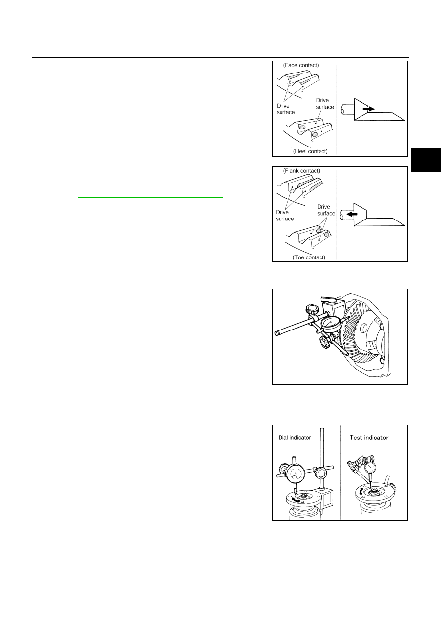
●
If the tooth contact is near the face (face contact), or near the
heel (heel contact), thicken pinion height adjusting washers to
move drive pinion closer to drive gear.
Refer to
FFD-36, "Pinion Height Adjusting Washer"
.
●
If the tooth contact is near the flank (flank contact), or near the
toe (toe contact), thin pinion height adjusting washers to move
drive pinion farther from drive gear.
Refer to
FFD-36, "Pinion Height Adjusting Washer"
.
Backlash
1.
Remove carrier cover. Refer to
FFD-20, "Differential Assembly"
2.
Fit a dial indicator to the drive gear face to measure the back-
lash.
●
If the backlash is outside of the specified value, change the
thickness of side bearing adjusting washer.
Companion Flange Runout
1.
Fit a dial indicator onto the companion flange face (inner side of
the propeller shaft mounting bolt holes).
2.
Rotate companion flange to check for runout.
3.
Fit a test indicator to the inner side of companion flange (socket
diameter).
4.
Rotate companion flange to check for runout.
5.
If the runout value is outside the runout limit, follow the proce-
dure below to adjust.
a.
Check for runout while changing the phase between companion flange and drive pinion by 90
°
step, and
search for the position where the runout is the minimum.
b.
If the runout value is still outside of the limit after the phase has been changed, possible cause will be an
assembly malfunction of drive pinion and pinion bearing and malfunction of pinion bearing. Check for
these items and repair if necessary.
PDIA0440E
PDIA0441E
Backlash:
0.10 - 0.15 mm (0.0039 - 0.0059 in)
When the backlash is large:
Decrease side bearing adjusting washer thickness.
Refer to
FFD-36, "Side Bearing Adjusting Washer"
.
When the backlash is small:
Increase side bearing adjusting washer thickness.
Refer to
FFD-36, "Side Bearing Adjusting Washer"
.
SDIA0009J
Runout limit:
0.18 mm (0.0070 in)
Runout limit:
0.13 mm (0.0051 in)
PDIA0646E