Infiniti M35/M45 Y50. Manual - part 762
FRONT DRIVE SHAFT
FAX-13
C
E
F
G
H
I
J
K
L
M
A
B
FAX
Disassembly and Assembly
NDS000G2
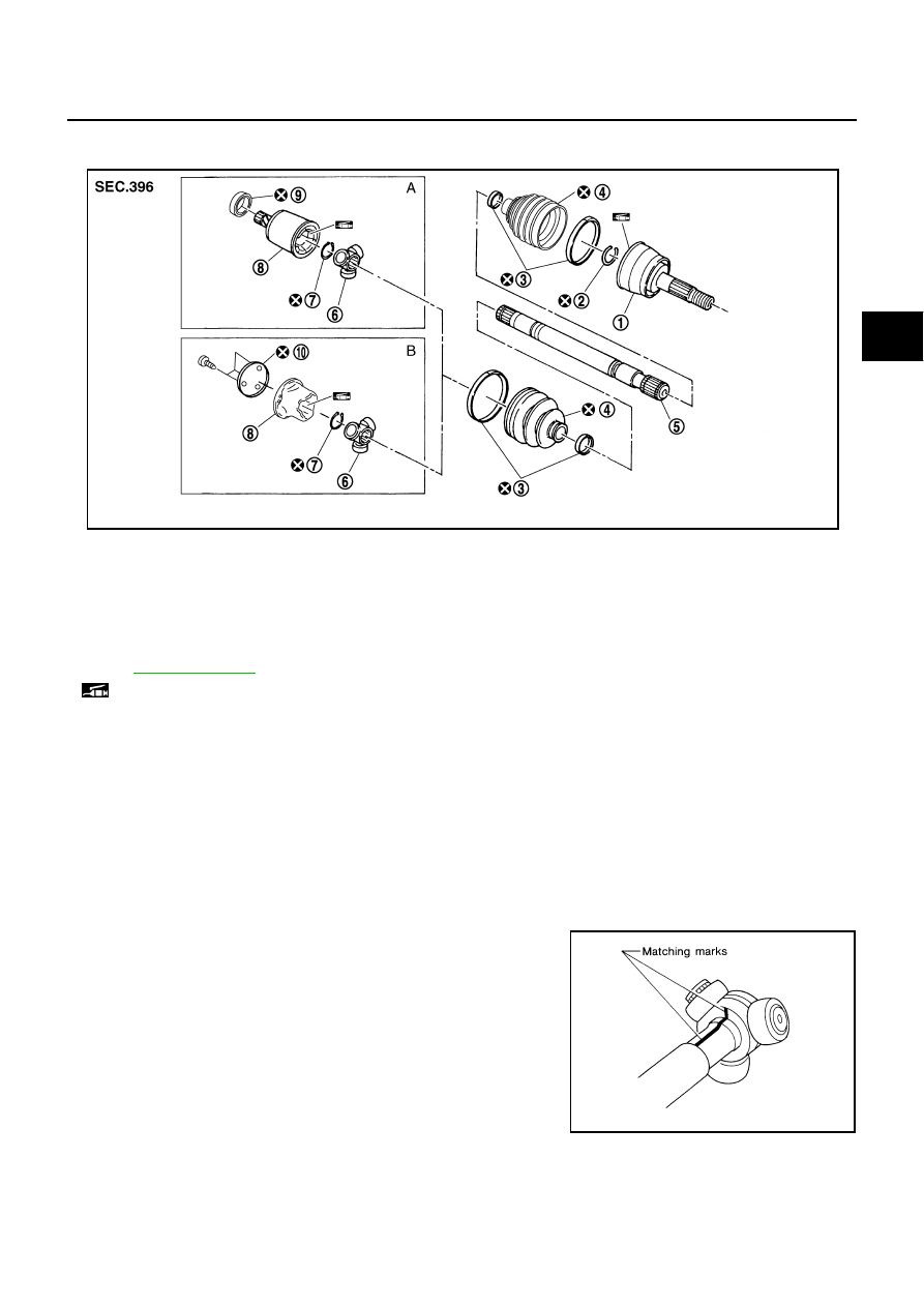
COMPONENT
DISASSEMBLY
Front Final Drive Side
1.
Place shaft in a vise.
CAUTION:
Protect shaft when securing in a vise using aluminum or copper plates.
2.
Remove boot bands, and then remove boot from housing.
3.
If plug needs to be removed, move boot to wheel side, and dive it out with a plastic hammer. (LH side)
4.
Put matching marks on housing and shaft, and then pull out housing from shaft.
CAUTION:
Use paint or similar substance for matching marks. Do not scratch the surfaces.
5.
Put matching marks on the shaft and spider assembly.
CAUTION:
Use paint or similar substance for matching marks. Do not
scratch the surfaces.
1.
Joint sub-assembly
2.
Circular clip
3.
Boot band
4.
Boot
5.
Shaft
6.
Spider assembly
7.
Snap ring
8.
Housing
9.
Dust shield
10. Plug
A: RH side
B: LH side
Refer to
and the following for the symbols in the figure.
: NISSAN genuine grease or equivalent
SDIA3043J
SFA963