Infiniti M35/M45 Y50. Manual - part 760


  Index      Infiniti     Infiniti M35/M45 Y50 - service repair manual 2007 year


Search            copyright infringement  


Content   ..  758  759  760  761   ..


Infiniti M35/M45 Y50. Manual - part 760


FRONT WHEEL HUB AND KNUCKLE

FAX-5

C

E

F

G

H

I

J

K

L

M

A

B

FAX

FRONT WHEEL HUB AND KNUCKLE

PFP:40202

On-Vehicle Inspection 

NDS000FF

Make sure that the mounting conditions (looseness, backlash) of each component and component conditions
(wear, damage) are normal.

WHEEL BEARING INSPECTION

Move wheel hub and bearing assembly in the axial direction by hand. Make sure there is no looseness of
wheel bearing.

Rotate wheel hub and make sure that is no unusual noise or other irregular conditions. If there is any of
irregular conditions, replace wheel hub and bearing assembly

Removal and Installation

NDS000FG

COMPONENT

REMOVAL
Wheel Hub and Bearing Assembly

1.

Remove tires from vehicle with power tool.

2.

Remove wheel sensor from steering knuckle. Refer to 

BRC-54, "WHEEL SENSOR"

 .

CAUTION:

Do not pull on wheel sensor harness.

3.

Remove brake hose bracket. Refer to 

BR-11, "BRAKE TUBE AND HOSE"

 .

4.

Remove torque member fixing bolts with power tool. Hang torque member in a place where it will not inter-
fere with work. Refer to 

BR-22, "FRONT DISC BRAKE"

 .

CAUTION:

Do not depress brake pedal while brake caliper is removed.

Axial end play

: 0.05 mm (0.002 in) or less
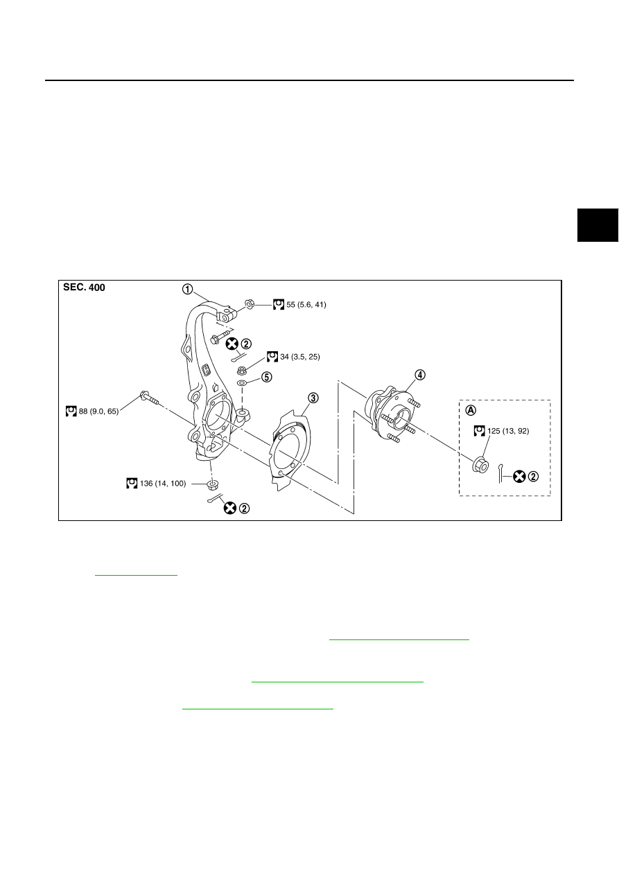
1.

Steering knuckle

2.

Cotter pin

3.

Splash guard

4.

Wheel hub and bearing assembly

5.

Washer

A: AWD 

models

Refer to 

GI-11, "Components"

 , for the symbols in the figure.

SDIA3256E

FAX-6

FRONT WHEEL HUB AND KNUCKLE

5.

Put matching mark on disc rotor and wheel hub and bearing
assembly, then remove disc rotor.

6.

Remove cotter pin, then loosen hub lock nut with power tool.
(AWD)

7.

Separate wheel hub and bearing assembly from drive shaft by
lightly tapping the end with a hammer (suitable tool) and a wood
block, and then remove hub lock nut. (AWD)

CAUTION:

Do not place drive shaft joint at an extreme angle. Also be
careful not to overextend slide joint.

Do not allow drive shaft to hang down without support for
housing (or joint sub-assembly), shaft and the other
parts.

NOTE:
Use a puller (suitable tool) if wheel hub and bearing assembly
and drive shaft cannot be separated even after performing the
above procedure.

8.

Remove wheel hub and bearing assembly mounting bolts, and then remove splash guard and wheel hub
and bearing assembly from steering knuckle.

Steering knuckle 

1.

Refer to the procedure from 1 to 7 in “Wheel Hub and Bearing Assembly” 

FAX-5, "REMOVAL"

 .

2.

Remove cotter pin (1), and then loosen the nut.

3.

Remove steering outer socket (2) from steering knuckle (3) so
as not to damage ball joint boot (4) using the ball joint remover
(suitable tool).

CAUTION:

Temporarily tighten the nut to prevent damage to threads
and to prevent the ball joint remover (suitable tool) from
suddenly coming off.

4.

Remove cotter pin of transverse link and steering knuckle, and
then loosen nut.

5.

Remove transverse link from steering knuckle so as not to dam-
age ball joint boot using the ball joint remover (suitable tool).

CAUTION:

Temporarily tighten the nut to prevent damage to threads and to prevent ball joint remover (suit-
able tool) from suddenly coming off.

6.

Remove fixing nut and bolt with power tool, and then remove steering knuckle from upper link. Refer to

FSU-8, "Components"

 .

7.

Remove wheel hub and bearing assembly mounting bolts, and then remove splash guard and wheel hub
and bearing assembly from steering knuckle.

INSPECTION AFTER REMOVAL

Check components for deformation, cracks, and other damage. Replace if there are.

Ball Joint Inspection

Check boots of transverse link and steering outer socket ball joint for breakage, axial play, and torque. Refer to

FSU-14, "INSPECTION AFTER REMOVAL"

 , “TRANSVERSE LINK”, 

PS-23, "INSPECTION AFTER DISAS-

SEMBLY"

 , “POWER STEERING GEAR”.

SDIA2608E

SDIA1821E

SGIA1183E

FRONT WHEEL HUB AND KNUCKLE

FAX-7

C

E

F

G

H

I

J

K

L

M

A

B

FAX

INSTALLATION

Installation is the reverse order of the removal. For tightening torque, refer to 

FAX-5, "COMPONENT"

 .

Perform the final tightening of each of parts under unladen conditions, which were removed when remov-
ing wheel hub and bearing assembly and steering knuckle. Check the wheel alignment. Refer to 

FSU-6,

"Wheel Alignment Inspection"

  (2WD), 

FSU-24, "Wheel Alignment Inspection"

  (AWD).

Adjust neutral position of steering angle sensor after checking the wheel alignment. Refer to 

BRC-6,

"Adjustment of Steering Angle Sensor Neutral Position"

 .

Check wheel sensor harness for proper connection. Refer to 

BRC-54, "WHEEL SENSOR"

 .

Assemble disc rotor and wheel hub and bearing assembly by
aligning each matching mark as shown in the figure when install-
ing disc rotor.

NOTE:
Refer to 

BR-27, "DISC ROTOR INSPECTION"

 , for assembly

when removing disc rotor without matching mark.

SDIA2608E

FAX-8

FRONT DRIVE SHAFT

FRONT DRIVE SHAFT

PFP:39100

On-Vehicle Inspection 

NDS000G0

Check drive shaft mounting point and joint for looseness and other damage.

Check boot for cracks and other damage.

CAUTION:

Replace entire drive shaft assembly when noise or vibration occur from drive shaft.

DRIVE SHAFT BOOT REPLACEMENT

1.

Remove tires from vehicle with power tool.

2.

Remove wheel sensor from steering knuckle. Refer to 

BRC-54, "WHEEL SENSOR"

 .

CAUTION:

Do not pull on wheel sensor harness.

3.

Remove brake hose bracket. Refer to 

BR-11, "BRAKE TUBE AND HOSE"

 .

4.

Remove torque member fixing bolts with power tool. Hang torque member in a place where it will not inter-
fere with work. Refer to 

BR-22, "FRONT DISC BRAKE"

 .

NOTE:
Do not depress brake pedal while brake caliper is removed.

5.

Remove disc rotor. Refer to 

FAX-5, "Removal and Installation"

 .

6.

Remove cotter pin, then loosen hub lock nut with power tool.

7.

Separate wheel hub and bearing assembly from drive shaft by
lightly tapping the end with a hammer (suitable tool) and a wood
block, and then remove hub lock nut.

CAUTION:

Do not place drive shaft joint at an extreme angle. Also be
careful not to overextend slide joint.

Do not allow drive shaft to hang down without support for
housing (or joint sub-assembly), shaft and the other
parts.

NOTE:
Use a puller (suitable tool) if wheel hub and drive shaft cannot
be separated even after performing the above procedure.

8.

Remove cotter pin (1), and then loosen the nut.

9.

Remove steering outer socket (2) from steering knuckle (3) so
as not to damage ball joint boot (4) using the ball joint remover
(suitable tool).

CAUTION:

Temporarily tighten the nut to prevent damage to threads
and to prevent the ball joint remover (suitable tool) from
suddenly coming off.

10. Remove cotter pin of transverse link and steering knuckle, and

then loosen nut.

11. Remove transverse link from steering knuckle so as not to dam-

age ball joint boot using the ball joint remover (suitable tool).

CAUTION:

Temporarily tighten the nut to prevent damage to threads and to prevent ball joint remover (suit-
able tool) from suddenly coming off.

12. Remove drive shaft from wheel hub and bearing assembly.

13. Remove boot bands, and then remove boot from joint sub-assembly.

SDIA1821E

SGIA1183E


Content   ..  758  759  760  761   ..