Infiniti M35/M45 Y50. Manual - part 736
IGNITION SIGNAL
EC-1417
[VK45DE]
C
D
E
F
G
H
I
J
K
L
M
A
EC
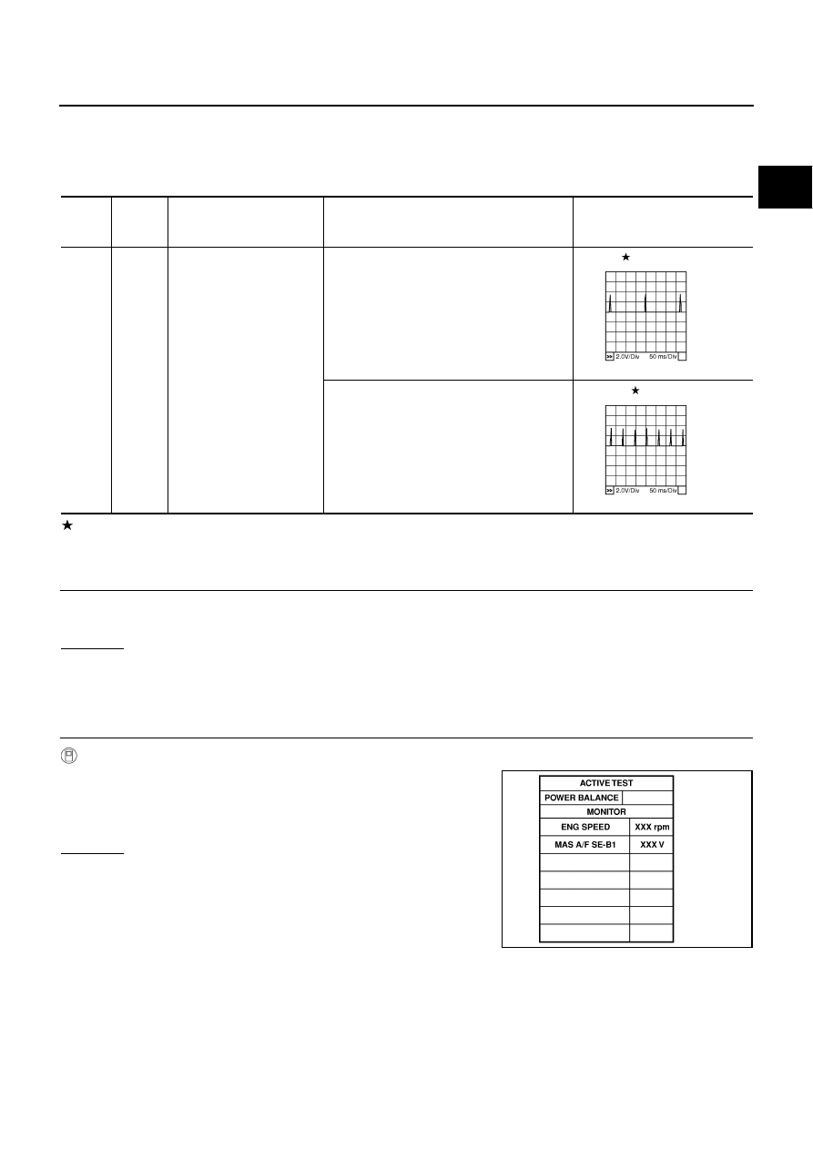
Specification data are reference values and are measured between each terminal and ground.
Pulse signal is measured by CONSULT-II.
CAUTION:
Do not use ECM ground terminals when measuring input/output voltage. Doing so may result in dam-
age to the ECM's transistor. Use a ground other than ECM terminals, such as the ground.
: Average voltage for pulse signal (Actual pulse signal can be confirmed by oscilloscope.)
Diagnostic Procedure
NBS005PS
1.
CHECK ENGINE START
Turn ignition switch OFF, and restart engine.
Is engine running?
Yes or No
Yes (With CONSULT-II)>>GO TO 2.
Yes (Without CONSULT-II)>>GO TO 3.
No
>> GO TO 4.
2.
CHECK OVERALL FUNCTION
With CONSULT-II
1.
Perform “POWER BALANCE” in “ACTIVE TEST” mode with
CONSULT-II.
2.
Make sure that each circuit produces a momentary engine
speed drop.
OK or NG
OK
>> INSPECTION END
NG
>> GO TO 10.
TER-
MINAL
NO.
WIRE
COLOR
ITEM
CONDITION
DATA (DC Voltage)
65
79
80
81
BR/R
GR/R
GR/B
G/R
Ignition signal No. 8
Ignition signal No. 6
Ignition signal No. 4
Ignition signal No. 2
[Engine is running]
●
Warm-up condition
●
Idle speed
NOTE:
The pulse cycle changes depending on rpm
at idle
0 - 0.2V
[Engine is running]
●
Warm-up condition
●
Engine speed: 2,000 rpm
0.1 - 0.4V
PBIB0044E
PBIB0045E
PBIB0133E