Infiniti M35/M45 Y50. Manual - part 731
FUEL PUMP
EC-1397
[VK45DE]
C
D
E
F
G
H
I
J
K
L
M
A
EC
Specification data are reference values and are measured between each terminal and ground.
CAUTION:
Do not use ECM ground terminals when measuring input/output voltage. Doing so may result in dam-
age to the ECM's transistor. Use a ground other than ECM terminals, such as the ground.
Diagnostic Procedure
NBS005Q4
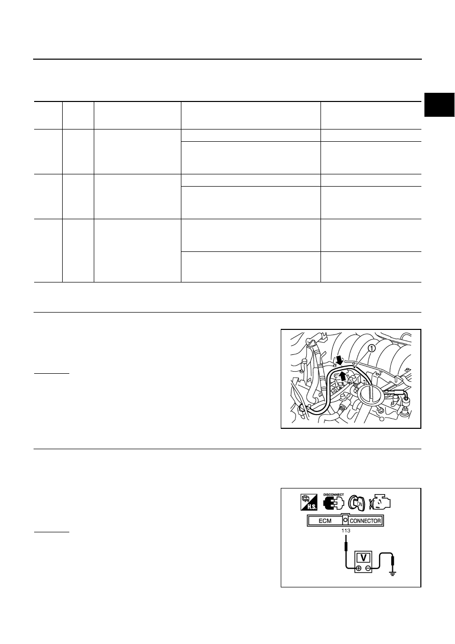
1.
CHECK OVERALL FUNCTION
1.
Turn ignition switch ON.
2.
Pinch fuel feed hose (1) with two fingers.
OK or NG
OK
>> INSPECTION END
NG
>> GO TO 2.
2.
CHECK FUEL PUMP POWER SUPPLY CIRCUIT-I
1.
Turn ignition switch OFF.
2.
Disconnect ECM harness connector.
3.
Turn ignition switch ON.
4.
Check voltage between ECM terminal 113 and ground with
CONSULT-II or tester.
OK or NG
OK
>> GO TO 5.
NG
>> GO TO 3.
TER-
MINAL
NO.
WIRE
COLOR
ITEM
CONDITION
DATA (DC Voltage)
38
G/B
Fuel pump control module
(FPCM) check
[When cranking engine]
Approximately 0V
[Engine is running]
●
Warm-up condition
●
Idle speed
4 - 6V
39
B/R
Fuel pump control module
(FPCM)
[When cranking engine]
0 - 0.5V
[Engine is running]
●
Warm-up condition
●
Idle speed
8 - 12V
113
GR
Fuel pump relay
[Ignition switch: ON]
●
For 1 second after turning ignition switch ON
[Engine is running]
0 - 1.5V
[Ignition switch: ON]
●
More than 1 second after turning ignition
switch ON
BATTERY VOLTAGE
(11 - 14V)
Fuel pressure pulsation should be felt on the fuel feed
hose for 1 second after ignition switch is turned ON.
PBIB2721E
Voltage: Battery voltage
PBIB1187E