Infiniti M35/M45 Y50. Manual - part 723
DTC P2A00, P2A03 A/F SENSOR 1
EC-1365
[VK45DE]
C
D
E
F
G
H
I
J
K
L
M
A
EC
DTC P2A00, P2A03 A/F SENSOR 1
PFP:22693
Component Description
NBS005PD
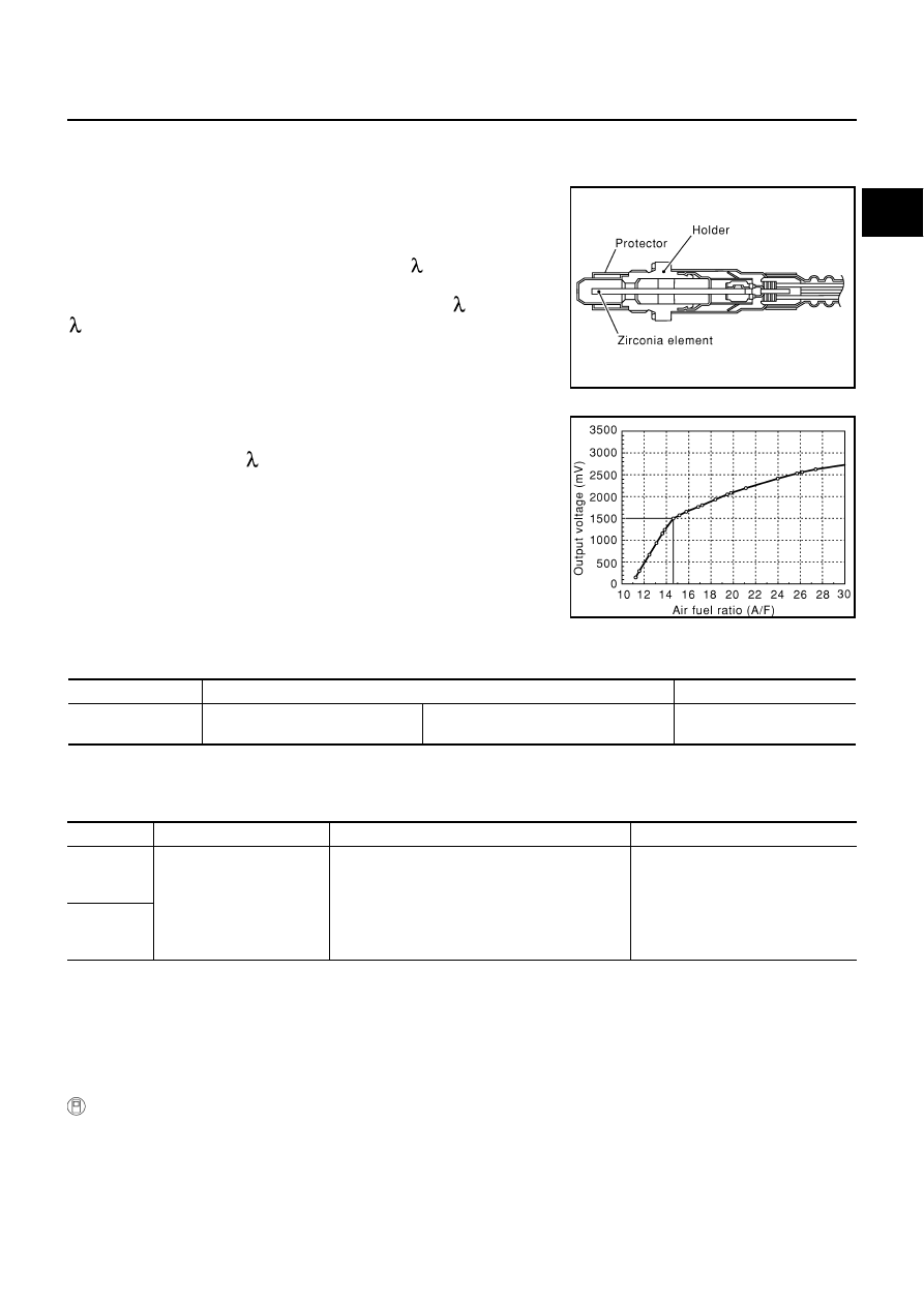
The air fuel ratio (A/F) sensor 1 is a planar dual-cell limit current sen-
sor. The sensor element of the A/F sensor 1 is the combination of a
Nernst concentration cell (sensor cell) with an oxygen-pump cell,
which transports ions. It has a heater in the element.
The sensor is capable of precise measurement = 1, but also in the
lean and rich range. Together with its control electronics, the sensor
outputs a clear, continuous signal throughout a wide range (0.7 <
< air).
The exhaust gas components diffuse through the diffusion gap at the
electrode of the oxygen pump and Nernst concentration cell, where
they are brought to thermodynamic balance.
An electronic circuit controls the pump current through the oxygen-
pump cell so that the composition of the exhaust gas in the diffusion
gap remains constant at = 1. Therefore, the A/F sensor 1 is able to
indicate air/fuel ratio by this pumping of current. In addition, a heater
is integrated in the sensor to ensure the required operating tempera-
ture of 700 - 800
°
C (1,292 - 1,472
°
F).
CONSULT-II Reference Value in Data Monitor Mode
NBS005PE
Specification data are reference values.
On Board Diagnosis Logic
NBS005PF
To judge the malfunction, the A/F signal computed by ECM from the A/F sensor 1 signal is monitored not to be
shifted to LEAN side or RICH side.
DTC Confirmation Procedure
NBS005PG
NOTE:
If DTC Confirmation Procedure has been previously conducted, always turn ignition switch OFF and wait at
least 10 seconds before conducting the next test.
TESTING CONDITION:
Before performing the following procedure, confirm that battery voltage is more than 11V at idle.
WITH CONSULT-II
1.
Start engine and warm it up to normal operating temperature.
2.
Turn ignition switch OFF and wait at least 10 seconds.
3.
Turn ignition switch ON and select “SELF-LEARNING CONT” in “WORK SUPPORT” mode with CON-
SULT-II.
SEF579Z
SEF580Z
MONITOR ITEM
CONDITION
SPECIFICATION
A/F SEN1 (B1)
A/F SEN1 (B2)
●
Engine: After warming up
Maintaining engine speed at 2,000 rpm
Fluctuates around 1.5 V
DTC No.
Trouble diagnosis name
DTC detecting condition
Possible Cause
P2A00
2A00
(Bank 1)
Air fuel ratio (A/F) sensor 1
circuit range/performance
●
The output voltage computed by ECM from the
A/F sensor 1 signal is shifted to the lean side
for a specified period.
●
The A/F signal computed by ECM from the A/F
sensor 1 signal is shifted to the rich side for a
specified period.
●
A/F sensor 1
●
A/F sensor 1 heater
●
Fuel pressure
●
Fuel injector
●
Intake air leaks
P2A03
2A03
(Bank 2)