Infiniti M35/M45 Y50. Manual - part 719
DTC P2127, P2128 APP SENSOR
EC-1349
[VK45DE]
C
D
E
F
G
H
I
J
K
L
M
A
EC
12.
CHECK APP SENSOR
Refer to
EC-1349, "Component Inspection"
.
OK or NG
OK
>> GO TO 14.
NG
>> GO TO 13.
13.
REPLACE ACCELERATOR PEDAL ASSEMBLY
1.
Replace accelerator pedal assembly.
2.
Perform
EC-788, "Accelerator Pedal Released Position Learning"
3.
Perform
EC-788, "Throttle Valve Closed Position Learning"
4.
Perform
EC-788, "Idle Air Volume Learning"
>> INSPECTION END
14.
CHECK INTERMITTENT INCIDENT
Refer to
EC-857, "TROUBLE DIAGNOSIS FOR INTERMITTENT INCIDENT"
>> INSPECTION END
Component Inspection
NBS005OV
ACCELERATOR PEDAL POSITION SENSOR
1.
Reconnect all harness connectors disconnected.
2.
Turn ignition switch ON.
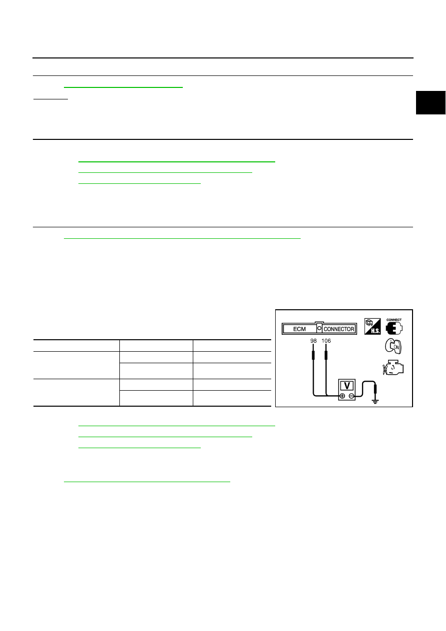
3.
Check voltage between ECM terminals 106 (APP sensor 1 sig-
nal), 98 (APP sensor 2 signal) and ground under the following
conditions.
4.
If NG, replace accelerator pedal assembly and go to next step.
5.
Perform
EC-788, "Accelerator Pedal Released Position Learning"
6.
Perform
EC-788, "Throttle Valve Closed Position Learning"
7.
Perform
EC-788, "Idle Air Volume Learning"
Removal and Installation
NBS005OW
ACCELERATOR PEDAL
Refer to
ACC-3, "ACCELERATOR CONTROL SYSTEM"
Terminal
Accelerator pedal
Voltage
106
(Accelerator pedal position
sensor 1)
Fully released
0.4 - 1.1V
Fully depressed
3.7 - 4.8V
98
(Accelerator pedal position
sensor 2)
Fully released
0.20 - 0.55V
Fully depressed
1.85 - 2.40V
MBIB0023E