Infiniti M35/M45 Y50. Manual - part 716


  Index      Infiniti     Infiniti M35/M45 Y50 - service repair manual 2007 year


Search            copyright infringement  


Content   ..  714  715  716  717   ..


Infiniti M35/M45 Y50. Manual - part 716


DTC P2122, P2123 APP SENSOR

EC-1337

[VK45DE]

C

D

E

F

G

H

I

J

K

L

M

A

EC

DTC Confirmation Procedure

NBS005OK

NOTE:
If DTC Confirmation Procedure has been previously conducted, always turn ignition switch OFF and wait at
least 10 seconds before conducting the next test.
TESTING CONDITION:
Before performing the following procedure, confirm that battery voltage is more than 8V at idle.

 WITH CONSULT-II

1.

Turn ignition switch ON.

2.

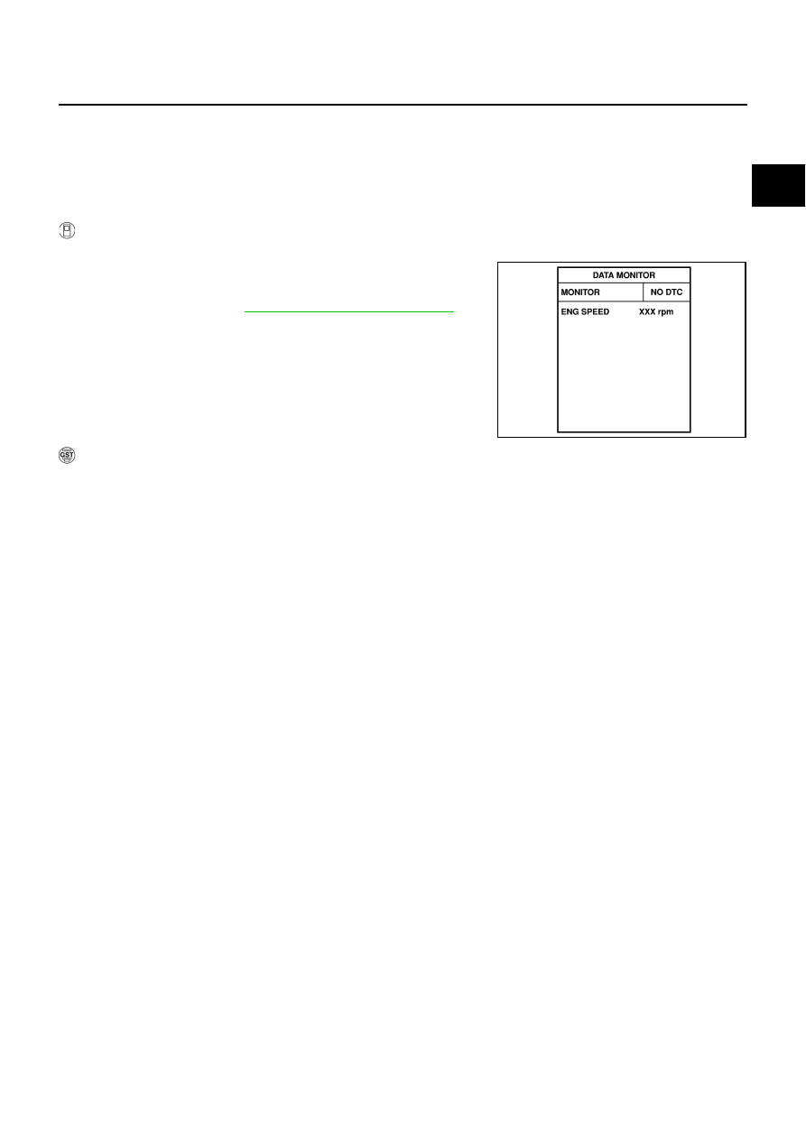
Select “DATA MONITOR” mode with CONSULT-II.

3.

Start engine and let it idle for 1 second.

4.

If DTC is detected, go to 

EC-1339, "Diagnostic Procedure"

 .

 WITH GST

Follow the procedure “WITH CONSULT-II” above.

SEF058Y

EC-1338

[VK45DE]

DTC P2122, P2123 APP SENSOR

Wiring Diagram

NBS005OL

TBWT1055E

DTC P2122, P2123 APP SENSOR

EC-1339

[VK45DE]

C

D

E

F

G

H

I

J

K

L

M

A

EC

Specification data are reference values and are measured between each terminal and ground.

CAUTION:

Do not use ECM ground terminals when measuring input/output voltage. Doing so may result in dam-
age to the ECM's transistor. Use a ground other than ECM terminals, such as the ground.

Diagnostic Procedure

NBS005OM

1. 

CHECK GROUND CONNECTIONS

1.

Turn ignition switch OFF.

2.

Loosen and retighten ground screws on the body.
Refer to 

EC-864, "Ground Inspection"

 .

OK or NG

OK

>> GO TO 2.

NG

>> Repair or replace ground connections.

TER-

MINAL 

NO.

WIRE 

COLOR

ITEM

CONDITION

DATA (DC Voltage)

82

W

Sensor ground
(APP sensor 1)

[Engine is running]

Warm-up condition

Idle speed

Approximately 0V

83

P

Sensor ground
(APP sensor 2)

[Engine is running]

Warm-up condition

Idle speed

Approximately 0V

90

L

Sensor power supply
(APP sensor 1)

[Ignition switch: ON]

Approximately 5V

91

BR

Sensor power supply
(APP sensor 2)

[Ignition switch: ON]

Approximately 5V

98

R

Accelerator pedal position 
sensor 2

[Ignition switch: ON]

Engine: Stopped

Accelerator pedal: Fully released

0.20 - 0.55V

[Ignition switch: ON]

Engine: Stopped

Accelerator pedal: Fully depressed

1.85 - 2.40V

106

LG

Accelerator pedal position 
sensor 1

[Ignition switch: ON]

Engine: Stopped

Accelerator pedal: Fully released

0.4 - 1.1V

[Ignition switch: ON]

Engine: Stopped

Accelerator pedal: Fully depressed

3.7 - 4.8V

1.

Body ground M70

2.

Body ground M16

PBIB2782E

EC-1340

[VK45DE]

DTC P2122, P2123 APP SENSOR

2. 

CHECK APP SENSOR 1 POWER SUPPLY CIRCUIT

1.

Disconnect accelerator pedal position (APP) sensor (1) harness
connector.

2.

Turn ignition switch ON.

3.

Check voltage between APP sensor terminal 4 and ground with
CONSULT-II or tester.

OK or NG

OK

>> GO TO 4.

NG

>> GO TO 3.

3. 

DETECT MALFUNCTIONING PART

Check the following.

Harness connectors E108, M15

Harness for open or short between ECM and accelerator pedal position sensor

>> Repair open circuit or short to ground or short to power in harness or connectors.

4. 

CHECK APP SENSOR 1 GROUND CIRCUIT FOR OPEN AND SHORT

1.

Turn ignition switch OFF.

2.

Disconnect ECM harness connector.

3.

Check harness continuity between APP sensor terminal 2 and ECM terminal 82.
Refer to Wiring Diagram.

4.

Also check harness for short to ground and short to power.

OK or NG

OK

>> GO TO 6.

NG

>> GO TO 5.

5. 

DETECT MALFUNCTIONING PART

Check the following.

Harness connectors E108, M15

Harness for open or short between ECM and accelerator pedal position sensor

>> Repair open circuit or short to ground or short to power in harness or connectors.

PBIB2704E

Voltage: Approximately 5V

PBIA9606J

Continuity should exist.


Content   ..  714  715  716  717   ..