Infiniti M35/M45 Y50. Manual - part 704


  Index      Infiniti     Infiniti M35/M45 Y50 - service repair manual 2007 year


Search            copyright infringement  


Content   ..  702  703  704  705   ..


Infiniti M35/M45 Y50. Manual - part 704


DTC P1572 ASCD BRAKE SWITCH

EC-1289

[VK45DE]

C

D

E

F

G

H

I

J

K

L

M

A

EC

DTC P1572 ASCD BRAKE SWITCH

PFP:25320

Component Description

NBS005MV

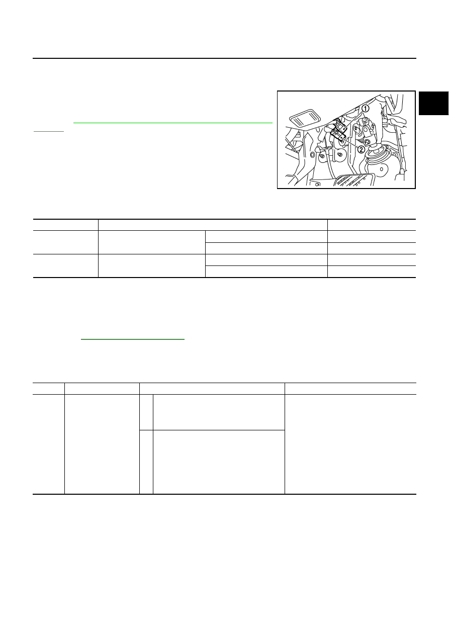
When the brake pedal is depressed, ASCD brake switch (2) is
turned OFF and stop lamp switch (1) is turned ON. ECM detects the
state of the brake pedal by this input of two kinds (ON/OFF signal).
Refer to 

EC-738, "AUTOMATIC SPEED CONTROL DEVICE

(ASCD)"

  for the ASCD function.

CONSULT-II Reference Value in Data Monitor Mode

NBS005MW

Specification data are reference values.

On Board Diagnosis Logic

NBS005MX

This self-diagnosis has the one trip detection logic.
The MIL will not light up for this diagnosis.

NOTE:

If DTC P1572 is displayed with DTC P0605, first perform the trouble diagnosis for DTC P0605.
Refer to 

EC-1190, "DTC P0605 ECM"

 .

This self-diagnosis has the one trip detection logic. When malfunction A is detected, DTC is not
stored in ECM memory. And in that case, 1st trip DTC and 1st trip freeze frame data are displayed.
1st trip DTC is erased when ignition switch OFF. And even when malfunction A is detected in two
consecutive trips, DTC is not stored in ECM memory.

PBIB2705E

MONITOR ITEM

CONDITION

SPECIFICATION

BRAKE SW1
(ASCD brake switch)

Ignition switch: ON

Brake pedal: Fully released

ON

Brake pedal: Slightly depressed

OFF

BRAKE SW2
(Stop lamp switch)

Ignition switch: ON

Brake pedal: Fully released

OFF

Brake pedal: Slightly depressed

ON

DTC No.

Trouble diagnosis name

DTC detecting condition

Possible cause

P1572
1572

ASCD brake switch

A)

When the vehicle speed is above 30 km/h 
(19 MPH), ON signals from the stop lamp 
switch and the ASCD brake switch are sent 
to the ECM at the same time.

Harness or connectors
(The stop lamp switch circuit is shorted.)

Harness or connectors
(The ASCD brake switch circuit is 
shorted.)

Stop lamp switch

ASCD brake switch

Incorrect stop lamp switch installation

Incorrect ASCD brake switch installation

ECM

B)

ASCD brake switch signal is not sent to 
ECM for extremely long time while the vehi-
cle is driving.

EC-1290

[VK45DE]

DTC P1572 ASCD BRAKE SWITCH

DTC Confirmation Procedure

NBS005MY

CAUTION:

Always drive vehicle at a safe speed.
NOTE:

If DTC Confirmation Procedure has been previously conducted, always turn ignition switch OFF and wait
at least 10 seconds before conducting the next test.

Procedure for malfunction B is not described here. It takes extremely long time to complete procedure for
malfunction B. By performing procedure for malfunction A, the incident that causes malfunction B can be
detected. 

TESTING CONDITION:
Steps 4 and 5 may be conducted with the drive wheels lifted in the shop or by driving the vehicle. If a
road test is expected to be easier, it is unnecessary to lift the vehicle.

 WITH CONSULT-II

1.

Start engine (VDC switch OFF).

2.

Select “DATA MONITOR” mode with CONSULT-II.

3.

Press MAIN switch and make sure that CRUISE lamp lights up.

4.

Drive the vehicle for at least 5 consecutive seconds under the
following conditions.

If 1st trip DTC is detected, go to 

EC-1292, "Diagnostic Proce-

dure"

 .

If 1st trip DTC is not detected, go to the following step.

5.

Drive the vehicle for at least 5 consecutive seconds under the following conditions.

6.

If 1st trip DTC is detected, go to 

EC-1292, "Diagnostic Procedure"

 .

 WITH GST

Follow the procedure “WITH CONSULT-II” above.

VHCL SPEED SE

More than 30 km/h (19 MPH)

Selector lever

Suitable position 

PBIB2386E

VHCL SPEED SE

More than 30 km/h (19 MPH)

Selector lever

Suitable position 

Driving location

Depress the brake pedal for more than 
five seconds so as not to come off from 
the above-mentioned vehicle speed.

DTC P1572 ASCD BRAKE SWITCH

EC-1291

[VK45DE]

C

D

E

F

G

H

I

J

K

L

M

A

EC

Wiring Diagram 

NBS005MZ

TBWT1050E

EC-1292

[VK45DE]

DTC P1572 ASCD BRAKE SWITCH

Specification data are reference values and are measured between each terminal and ground.

CAUTION:

Do not use ECM ground terminals when measuring input/output voltage. Doing so may result in dam-
age to the ECM's transistor. Use a ground other than ECM terminals, such as the ground.

Diagnostic Procedure

NBS005N0

1. 

CHECK OVERALL FUNCTION-I

 With CONSULT-II

1.

Turn ignition switch ON.

2.

Select “BRAKE SW1” in “DATA MONITOR” mode with CONSULT-II.

3.

Check “BRAKE SW1” indication under the following conditions.

 Without CONSULT-II

1.

Turn ignition switch ON.

2.

Check voltage between ECM terminal 108 and ground under the
following conditions.

OK or NG

OK

>> GO TO 2.

NG

>> GO TO 3.

TER-

MINAL 

NO.

WIRE 

COLOR

ITEM

CONDITION

DATA (DC Voltage)

101

V/R

Stop lamp switch

[Ignition switch: OFF]

Brake pedal: Fully released

Approximately 0V

[Ignition switch: OFF]

Brake pedal: Slightly depressed

BATTERY VOLTAGE
(11 - 14V)

108

BR

ASCD brake switch

[Ignition switch: ON]

Brake pedal: Slightly depressed

Approximately 0V

[Ignition switch: ON]

Brake pedal: Fully released

BATTERY VOLTAGE
(11 - 14V)

CONDITION

INDICATION

Brake pedal: Slightly depressed

OFF

Brake pedal: Fully released

ON

SEC011D

CONDITION

VOLTAGE

Brake pedal: Slightly depressed

Approximately 0V

Brake pedal: Fully released

Battery voltage

MBIB0061E


Content   ..  702  703  704  705   ..