Infiniti M35/M45 Y50. Manual - part 702


  Index      Infiniti     Infiniti M35/M45 Y50 - service repair manual 2007 year


Search            copyright infringement  


Content   ..  700  701  702  703   ..


Infiniti M35/M45 Y50. Manual - part 702


DTC P1572 ICC BRAKE SWITCH

EC-1281

[VK45DE]

C

D

E

F

G

H

I

J

K

L

M

A

EC

DTC Confirmation Procedure

NBS005MR

CAUTION:

Always drive vehicle at a safe speed.
NOTE:

If DTC Confirmation Procedure has been previously conducted, always turn ignition switch OFF and wait
at least 10 seconds before conducting the next test.

Procedure for malfunction B is not described here. It takes extremely long time to complete procedure for
malfunction B. By performing procedure for malfunction A, the incident that causes malfunction B can be
detected. 

TESTING CONDITION:
Steps 4 and 5 may be conducted with the drive wheels lifted in the shop or by driving the vehicle. If a
road test is expected to be easier, it is unnecessary to lift the vehicle.

 WITH CONSULT-II

1.

Start engine (VDC switch OFF).

2.

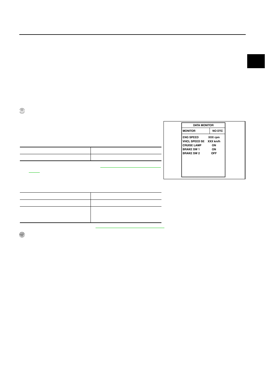
Select “DATA MONITOR” mode with CONSULT-II.

3.

Press MAIN switch and make sure that CRUISE lamp lights up.

4.

Drive the vehicle for at least 5 consecutive seconds under the
following conditions.

If 1st trip DTC is detected, go to 

EC-1283, "Diagnostic Proce-

dure"

 .

If 1st trip DTC is not detected, go to the following step.

5.

Drive the vehicle for at least 5 consecutive seconds under the following conditions.

6.

If 1st trip DTC is detected, go to 

EC-1283, "Diagnostic Procedure"

 .

 WITH GST

Follow the procedure “WITH CONSULT-II” above.

VHCL SPEED SE

More than 30 km/h (19 MPH)

Selector lever

Suitable position 

PBIB2386E

VHCL SPEED SE

More than 30 km/h (19 MPH)

Selector lever

Suitable position 

Driving location

Depress the brake pedal for more than 
five seconds so as not to come off from 
the above-mentioned vehicle speed.

EC-1282

[VK45DE]

DTC P1572 ICC BRAKE SWITCH

Wiring Diagram 

NBS005MS

TBWT1051E

DTC P1572 ICC BRAKE SWITCH

EC-1283

[VK45DE]

C

D

E

F

G

H

I

J

K

L

M

A

EC

Specification data are reference values and are measured between each terminal and ground.

CAUTION:

Do not use ECM ground terminals when measuring input/output voltage. Doing so may result in dam-
age to the ECM's transistor. Use a ground other than ECM terminals, such as the ground.

Diagnostic Procedure

NBS005MT

1. 

CHECK OVERALL FUNCTION-I

 With CONSULT-II

1.

Turn ignition switch ON.

2.

Select “BRAKE SW1” in “DATA MONITOR” mode with CON-
SULT-II.

3.

Check “BRAKE SW1” indication under the following conditions.

 Without CONSULT-II

1.

Turn ignition switch ON.

2.

Check voltage between ECM terminal 108 and ground under the
following conditions.

OK or NG

OK

>> GO TO 2.

NG

>> GO TO 3.

TER-

MINAL 

NO.

WIRE 

COLOR

ITEM

CONDITION

DATA (DC Voltage)

101

V/R

Stop lamp switch

[Ignition switch: OFF]

Brake pedal: Fully released

Approximately 0V

[Ignition switch: OFF]

Brake pedal: Slightly depressed

BATTERY VOLTAGE
(11 - 14V)

108

BR

ICC brake switch

[Ignition switch: ON]

Brake pedal: Slightly depressed

Approximately 0V

[Ignition switch: ON]

Brake pedal: Fully released

BATTERY VOLTAGE
(11 - 14V)

CONDITION

INDICATION

Brake pedal: Slightly depressed

OFF

Brake pedal: Fully released

ON

SEC011D

CONDITION

VOLTAGE

Brake pedal: Slightly depressed

Approximately 0V

Brake pedal: Fully released

Battery voltage

MBIB0061E

EC-1284

[VK45DE]

DTC P1572 ICC BRAKE SWITCH

2. 

CHECK OVERALL FUNCTION-II

 With CONSULT-II

Check “BRAKE SW2” indication in “DATA MONITOR” mode. 

 Without CONSULT-II

Check voltage between ECM terminal 101 and ground under the fol-
lowing conditions.

OK or NG

OK

>> GO TO 15.

NG

>> GO TO 8.

3. 

CHECK ICC BRAKE SWITCH POWER SUPPLY CIRCUIT

1.

Turn ignition switch OFF.

2.

Disconnect ICC brake switch (2) harness connector.

Stop lamp switch (1)

3.

Turn ignition switch ON.

4.

Check voltage between ICC brake switch terminal 1 and ground
with CONSULT-II or tester.

OK or NG

OK

>> GO TO 5.

NG

>> GO TO 4.

CONDITION

INDICATION

Brake pedal: Fully released

OFF

Brake pedal: Slightly depressed

ON

SEC013D

CONDITION

VOLTAGE

Brake pedal: Fully released

Approximately 0V

Brake pedal: Slightly depressed

Battery voltage

PBIB1537E

PBIB2705E

Voltage: Battery voltage

PBIB0857E


Content   ..  700  701  702  703   ..