Infiniti M35/M45 Y50. Manual - part 696
DTC P1553 BATTERY CURRENT SENSOR
EC-1257
[VK45DE]
C
D
E
F
G
H
I
J
K
L
M
A
EC
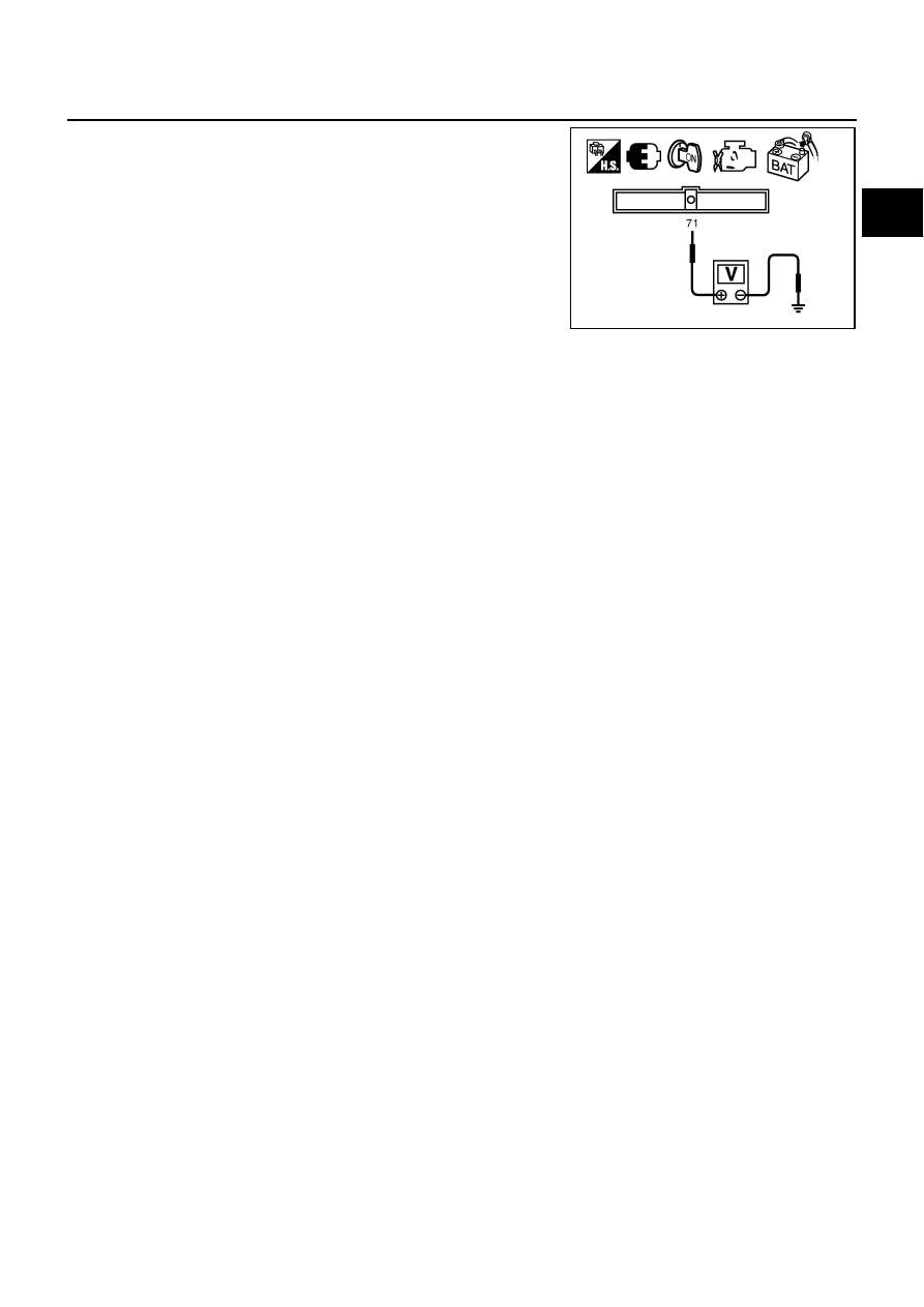
5.
Check voltage between ECM terminal 71 (battery current sensor
signal) and ground.
6.
If NG, replace battery negative cable assembly.
Voltage: Approximately 2.5V
PBIB2617E