Infiniti M35/M45 Y50. Manual - part 617


  Index      Infiniti     Infiniti M35/M45 Y50 - service repair manual 2007 year


Search            copyright infringement  


Content   ..  615  616  617  618   ..


Infiniti M35/M45 Y50. Manual - part 617


DTC P0125 ECT SENSOR

EC-941

[VK45DE]

C

D

E

F

G

H

I

J

K

L

M

A

EC

3. 

CHECK THERMOSTAT OPERATION

When the engine is cold [lower than 70

°

C (158

°

F)] condition, grasp lower radiator hose and confirm the engine

coolant does not flow.

OK or NG

OK

>> GO TO 4.

NG

>> Repair or replace thermostat. Refer to 

CO-55, "THERMOSTAT AND WATER CONTROL VALVE"

 .

4. 

CHECK INTERMITTENT INCIDENT

Refer to 

EC-857, "TROUBLE DIAGNOSIS FOR INTERMITTENT INCIDENT"

 .

Refer to 

EC-928, "Wiring Diagram"

 .

>> INSPECTION END

Component Inspection

NBS005DC

ENGINE COOLANT TEMPERATURE SENSOR

1.

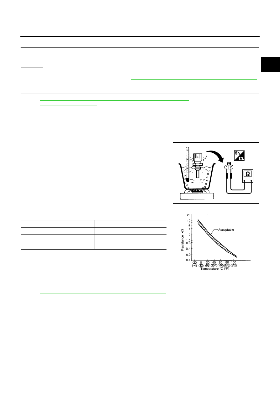
Check resistance between engine coolant temperature sensor
terminals 1 and 2 as shown in the figure.

<Reference data>

2.

If NG, replace engine coolant temperature sensor.

Removal and Installation

NBS005DD

ENGINE COOLANT TEMPERATURE SENSOR

Refer to 

CO-55, "THERMOSTAT AND WATER CONTROL VALVE"

 .

PBIB2005E

Temperature

°

C (

°

F)

Resistance

k

20 (68)

2.1 - 2.9

50 (122)

0.68 - 1.00

90 (194)

0.236 - 0.260

SEF012P

EC-942

[VK45DE]

DTC P0127 IAT SENSOR

DTC P0127 IAT SENSOR

PFP:22630

Component Description

NBS005DE

The intake air temperature sensor is built-into mass air flow sensor
(1). The sensor detects intake air temperature and transmits a signal
to the ECM.
The temperature sensing unit uses a thermistor which is sensitive to
the change in temperature. Electrical resistance of the thermistor
decreases in response to the temperature rise.

<Reference data>

*: This data is reference value and is measured between ECM terminal 34 (Intake air
temperature sensor) and ground.

CAUTION:

Do not use ECM ground terminals when measuring input/output
voltage. Doing so may result in damage to the ECM's transistor.
Use a ground other than ECM terminals, such as the ground.

On Board Diagnosis Logic

NBS005DF

DTC Confirmation Procedure

NBS005DG

NOTE:
If DTC Confirmation Procedure has been previously conducted, always turn ignition switch OFF and wait at
least 10 seconds before conducting the next test.

CAUTION:

Always drive vehicle at a safe speed.
TESTING CONDITION:
This test may be conducted with the drive wheels lifted in the shop or by driving the vehicle. If a road
test is expected to be easier, it is unnecessary to lift the vehicle.

 WITH CONSULT-II

1.

Wait until engine coolant temperature is less than 90

°

C (194

°

F)

a.

Turn ignition switch ON.

PBIA9559J

Intake air temperature

°

C (

°

F)

Voltage*

V

Resistance

k

25 (77)

3.3

1.800 - 2.200

80 (176)

1.2

0.283 - 0.359

SEF012P

DTC No.

Trouble diagnosis name

DTC detecting condition

Possible cause

P0127
0127

Intake air temperature 
too high

Rationally incorrect voltage from the sensor is 
sent to ECM, compared with the voltage signal 
from engine coolant temperature sensor.

Harness or connectors
(The sensor circuit is open or shorted)

Intake air temperature sensor

DTC P0127 IAT SENSOR

EC-943

[VK45DE]

C

D

E

F

G

H

I

J

K

L

M

A

EC

b.

Select “DATA MONITOR” mode with CONSULT-II.

c.

Check the engine coolant temperature.

d.

If the engine coolant temperature is not less than 90

°

C (194

°

F),

turn ignition switch OFF and cool down engine.

Perform the following steps before engine coolant tempera-
ture is above 90

°

C (194

°

F).

2.

Turn ignition switch ON.

3.

Select “DATA MONITOR” mode with CONSULT-II.

4.

Start engine.

5.

Hold vehicle speed at more than 70 km/h (43 MPH) for 100 con-
secutive seconds.

6.

If 1st trip DTC is detected, go to 

EC-943, "Diagnostic Procedure"

 .

 WITH GST

Follow the procedure “WITH CONSULT-II” above.

Diagnostic Procedure

NBS005DH

1. 

CHECK GROUND CONNECTIONS

1.

Turn ignition switch OFF.

2.

Loosen and retighten ground screws on the body.
Refer to 

EC-864, "Ground Inspection"

 .

OK or NG

OK

>> GO TO 2.

NG

>> Repair or replace ground connections.

2. 

CHECK INTAKE AIR TEMPERATURE SENSOR

Refer to 

EC-944, "Component Inspection"

 .

OK or NG

OK

>> GO TO 3.

NG

>> Replace mass air flow sensor (with intake air temperature sensor).

3. 

CHECK INTERMITTENT INCIDENT

Refer to 

EC-857, "TROUBLE DIAGNOSIS FOR INTERMITTENT INCIDENT"

 .

Refer to 

EC-923, "Wiring Diagram"

 .

>> INSPECTION END

SEF189Y

1.

Body ground M70

2.

Body ground M16

PBIB2782E

EC-944

[VK45DE]

DTC P0127 IAT SENSOR

Component Inspection

NBS005DI

INTAKE AIR TEMPERATURE SENSOR

1.

Check resistance between mass air flow sensor (1) terminals 5
and 6 under the following conditions.

2.

If NG, replace mass air flow sensor (with intake air temperature
sensor).

Removal and Installation

NBS005DJ

MASS AIR FLOW SENSOR

Refer to 

EM-177, "AIR CLEANER AND AIR DUCT"

 .

Intake air temperature 

°

C (

°

F)

Resistance k

25 (77)

1.800 - 2.200

PBIA9559J

SEF012P


Content   ..  615  616  617  618   ..