Infiniti M35/M45 Y50. Manual - part 565
ENGINE CONTROL SYSTEM
EC-733
[VK45DE]
C
D
E
F
G
H
I
J
K
L
M
A
EC
Multiport Fuel Injection (MFI) System
NBS0059J
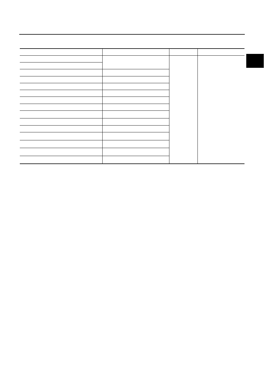
INPUT/OUTPUT SIGNAL CHART
*1: This sensor is not used to control the engine system under normal conditions.
*2: This signal is sent to the ECM through CAN communication line.
*3: ECM determines the start signal status by the signals of engine speed and battery voltage.
SYSTEM DESCRIPTION
The amount of fuel injected from the fuel injector is determined by the ECM. The ECM controls the length of
time the valve remains open (injection pulse duration). The amount of fuel injected is a program value in the
ECM memory. The program value is preset by engine operating conditions. These conditions are determined
by input signals (for engine speed and intake air) from the crankshaft position sensor (POS), camshaft position
sensor (PHASE) and the mass air flow sensor.
VARIOUS FUEL INJECTION INCREASE/DECREASE COMPENSATION
In addition, the amount of fuel injected is compensated to improve engine performance under various operat-
ing conditions as listed below.
<Fuel increase>
●
During warm-up
●
When starting the engine
●
During acceleration
●
Hot-engine operation
●
When selector lever is changed from N to D
●
High-load, high-speed operation
<Fuel decrease>
●
During deceleration
●
During high engine speed operation
Sensor
Input Signal to ECM
ECM function
Actuator
Crankshaft position sensor (POS)
Engine speed*
3
Piston position
Fuel injection
& mixture ratio
control
Fuel injector
Camshaft position sensor (PHASE)
Mass air flow sensor
Amount of intake air
Engine coolant temperature sensor
Engine coolant temperature
Air fuel ratio (A/F) sensor 1
Density of oxygen in exhaust gas
Throttle position sensor
Throttle position
Accelerator pedal position sensor
Accelerator pedal position
Park/neutral position (PNP) switch
Gear position
Battery
Battery voltage*
3
Knock sensor
Engine knocking condition
Power steering pressure sensor
Power steering operation
Heated oxygen sensor 2*
1
Density of oxygen in exhaust gas
ABS actuator and electric unit (control unit)
VDC/TCS operation command*
2
Air conditioner switch
Air conditioner operation*
2
Wheel sensor
Vehicle speed*
2