Infiniti M35/M45 Y50. Manual - part 547


  Index      Infiniti     Infiniti M35/M45 Y50 - service repair manual 2007 year


Search            copyright infringement  


Content   ..  545  546  547  548   ..


Infiniti M35/M45 Y50. Manual - part 547


ASCD BRAKE SWITCH

EC-661

[VQ35DE]

C

D

E

F

G

H

I

J

K

L

M

A

EC

3. 

CHECK ASCD BRAKE SWITCH POWER SUPPLY CIRCUIT

1.

Turn ignition switch OFF.

2.

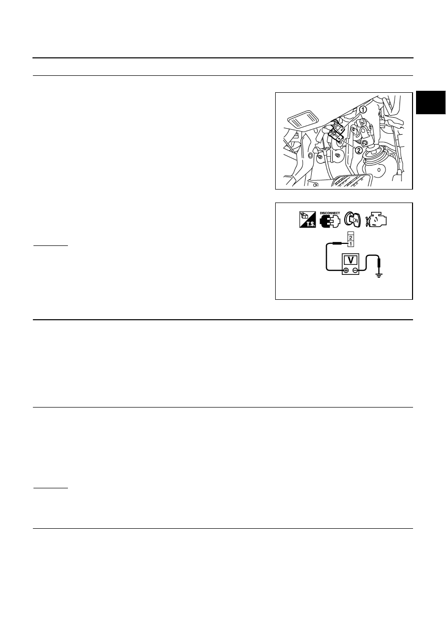
Disconnect ASCD brake switch (2) harness connector.

Stop lamp switch (1)

3.

Turn ignition switch ON.

4.

Check voltage between ASCD brake switch terminal 1 and
ground with CONSULT-II or tester.

OK or NG

OK

>> GO TO 5.

NG

>> GO TO 4.

4. 

DETECT MALFUNCTIONING PART

Check the following.

Fuse block (J/B) connector E102

10A fuse

Harness for open or short between ASCD brake switch and fuse

>> Repair open circuit or short to ground or short to power in harness or connectors.

5. 

CHECK ASCD BRAKE SWITCH INPUT SIGNAL CIRCUIT FOR OPEN AND SHORT

1.

Turn ignition switch OFF.

2.

Disconnect ECM harness connector.

3.

Check harness continuity between ECM terminal 108 and ASCD brake switch terminal 2.
Refer to Wiring Diagram.

4.

Also check harness for short to ground and short to power.

OK or NG

OK

>> GO TO 7.

NG

>> GO TO 6.

6. 

DETECT MALFUNCTIONING PART

Check the following.

Harness connectors E108, M15

Harness for open or short between ECM and ASCD brake switch

>> Repair open circuit or short to ground or short to power in harness or connectors.

PBIB2705E

Voltage: Battery voltage

PBIB0857E

Continuity should exist.

EC-662

[VQ35DE]

ASCD BRAKE SWITCH

7. 

CHECK ASCD BRAKE SWITCH

Refer to 

EC-663, "Component Inspection"


OK or NG

OK

>> GO TO 13.

NG

>> Replace ASCD brake switch.

8. 

CHECK STOP LAMP SWITCH POWER SUPPLY CIRCUIT

1.

Turn ignition switch OFF.

2.

Disconnect stop lamp switch (1) harness connector.

ASCD brake switch (2)

3.

Check voltage between stop lamp switch terminal 1 and ground
with CONSULT -II or tester.

OK or NG

OK

>> GO TO 10.

NG

>> GO TO 9.

9. 

DETECT MALFUNCTIONING PART

Check the following.

Fuse block (J/B) connector E101

10A fuse

Harness for open or short between stop lamp switch and battery

>> Repair open circuit or short to ground or short to power in harness or connectors.

10. 

CHECK STOP LAMP SWITCH INPUT SIGNAL CIRCUIT FOR OPEN AND SHORT

1.

Disconnect ECM harness connector.

2.

Check harness continuity between ECM terminal 101 and stop lamp switch terminal 2.
Refer to Wiring Diagram.

3.

Also check harness for short to ground and short to power.

OK or NG

OK

>> GO TO 12.

NG

>> GO TO 11.

PBIB2705E

Voltage: Battery voltage

PBIA9488J

Continuity should exist.

ASCD BRAKE SWITCH

EC-663

[VQ35DE]

C

D

E

F

G

H

I

J

K

L

M

A

EC

11. 

DETECT MALFUNCTIONING PART

Check the following.

Harness connectors E108, M15

Harness for open or short between ECM and stop lamp switch

>> Repair open circuit or short to ground or short to power in harness or connectors.

12. 

CHECK STOP LAMP SWITCH

Refer to 

EC-663, "Component Inspection"

 .

OK or NG

OK

>> GO TO 13.

NG

>> Replace stop lamp switch.

13. 

CHECK INTERMITTENT INCIDENT

Refer to 

EC-153, "TROUBLE DIAGNOSIS FOR INTERMITTENT INCIDENT"

 .

>> INSPECTION END

Component Inspection

NBS0058L

ASCD BRAKE SWITCH

1.

Turn ignition switch OFF.

2.

Disconnect ASCD brake switch harness connector.

3.

Check harness continuity between ASCD brake switch terminals
1 and 2 under the following conditions.

4.

If NG, adjust ASCD brake switch installation, refer to 

BR-6,

"BRAKE PEDAL"

 , and perform step 3 again.

STOP LAMP SWITCH

1.

Turn ignition switch OFF.

2.

Disconnect stop lamp switch harness connector.

3.

Check harness continuity between stop lamp switch terminals 1
and 2 under the following conditions.

4.

If NG, adjust stop lamp switch installation, refer to 

BR-6,

"BRAKE PEDAL"

 , and perform step 3 again.

Condition

Continuity

Brake pedal: Fully released.

Should exist.

Brake pedal: Slightly depressed.

Should not exist.

PBIB1536E

Condition

Continuity

Brake pedal: Fully released.

Should not exist.

Brake pedal: Slightly depressed.

Should exist.

PBIA9489J

EC-664

[VQ35DE]

ASCD INDICATOR

ASCD INDICATOR

PFP:24814

Component Description

NBS0058M

ASCD indicator lamp illuminates to indicate ASCD operation status. Lamp has two indicators, CRUISE and
SET, and is integrated in combination meter.
CRUISE lamp illuminates when MAIN switch on ASCD steering switch is turned ON to indicated that ASCD
system is ready for operation.
SET lamp illuminates when following conditions are met. 

CRUISE lamp is illuminated.

SET/COAST switch on ASCD steering switch is turned ON while vehicle speed is within the range of
ASCD setting.

SET lamp remains lit during ASCD control.
Refer to 

EC-36, "AUTOMATIC SPEED CONTROL DEVICE (ASCD)"

  for the ASCD function.

CONSULT-II Reference Value in Data Monitor Mode

NBS0058N

Specification data are reference values.

MONITOR ITEM

CONDITION

SPECIFICATION

CRUISE LAMP

Ignition switch: ON

MAIN switch: Pressed at the 1st time 


at the 2nd time

ON 

 OFF

SET LAMP

MAIN switch: ON

When vehicle speed is between 
40 km/h (25 MPH) and 144 km/h 
(89 MPH)

ASCD: Operating

ON

ASCD: Not operating

OFF


Content   ..  545  546  547  548   ..