Infiniti M35/M45 Y50. Manual - part 534


  Index      Infiniti     Infiniti M35/M45 Y50 - service repair manual 2007 year


Search            copyright infringement  


Content   ..  532  533  534  535   ..


Infiniti M35/M45 Y50. Manual - part 534


DTC P2101 ELECTRIC THROTTLE CONTROL FUNCTION

EC-609

[VQ35DE]

C

D

E

F

G

H

I

J

K

L

M

A

EC

11. 

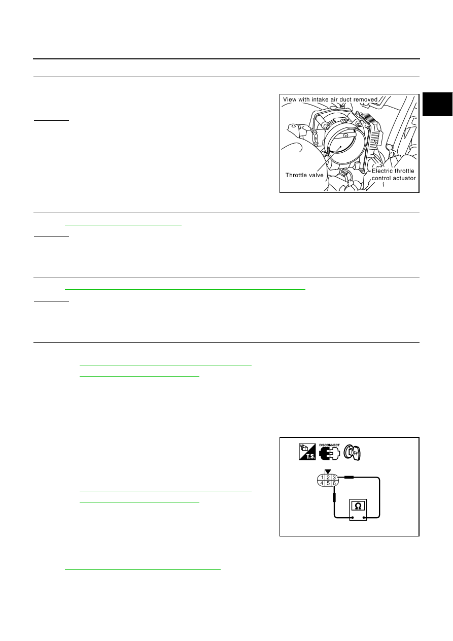
CHECK ELECTRIC THROTTLE CONTROL ACTUATOR VISUALLY 

1.

Remove the intake air duct.

2.

Check if foreign matter is caught between the throttle valve and
the housing.

OK or NG

OK

>> GO TO 12.

NG

>> Remove the foreign matter and clean the electric throttle

control actuator inside.

12. 

CHECK THROTTLE CONTROL MOTOR

Refer to 

EC-609, "Component Inspection"

 .

OK or NG

OK

>> GO TO 13.

NG

>> GO TO 14.

13. 

CHECK INTERMITTENT INCIDENT

Refer to 

EC-153, "TROUBLE DIAGNOSIS FOR INTERMITTENT INCIDENT"

 .

OK or NG

OK

>> GO TO 14.

NG

>> Repair or replace harness or connectors.

14. 

REPLACE ELECTRIC THROTTLE CONTROL ACTUATOR

1.

Replace the electric throttle control actuator.

2.

Perform 

EC-86, "Throttle Valve Closed Position Learning"

 .

3.

Perform 

EC-86, "Idle Air Volume Learning"

 .

>> INSPECTION END

Component Inspection

NBS00568

THROTTLE CONTROL MOTOR

1.

Disconnect electric throttle control actuator harness connector.

2.

Check resistance between terminals 3 and 6.

3.

If NG, replace electric throttle control actuator and go to next
step.

4.

Perform 

EC-86, "Throttle Valve Closed Position Learning"

 .

5.

Perform 

EC-86, "Idle Air Volume Learning"

 .

Removal and Installation

NBS00569

ELECTRIC THROTTLE CONTROL ACTUATOR

Refer to 

EM-21, "INTAKE MANIFOLD COLLECTOR"

 .

PBIB1556E

Resistance: Approximately 1 - 15 

 [at 25 

°

C (77

°

F)]

PBIB0095E

EC-610

[VQ35DE]

DTC P2118 THROTTLE CONTROL MOTOR

DTC P2118 THROTTLE CONTROL MOTOR

PFP:16119

Component Description

NBS0056A

The throttle control motor is operated by the ECM and it opens and closes the throttle valve.
The current opening angle of the throttle valve is detected by the throttle position sensor and it provides feed-
back to the ECM to control the throttle control motor to make the throttle valve opening angle properly in
response to driving condition.

On Board Diagnosis Logic

NBS0056B

This self-diagnosis has the one trip detection logic.

FAIL-SAFE MODE

When the malfunction is detected, ECM enters fail-safe mode and the MIL lights up.

DTC Confirmation Procedure

NBS0056C

NOTE:
If DTC Confirmation Procedure has been previously conducted, always turn ignition switch OFF and wait at
least 10 seconds before conducting the next test.

 WITH CONSULT-II

1.

Turn ignition switch ON and wait at least 2 seconds.

2.

Select “DATA MONITOR” mode with CONSULT-II.

3.

Start engine and let it idle for 5 seconds.

4.

If DTC is detected, go to 

EC-612, "Diagnostic Procedure"

 .

 WITH GST

Follow the procedure “WITH CONSULT-II” above.

DTC No.

Trouble diagnosis name

DTC detecting condition

Possible cause

P2118
2118

Throttle control motor 
circuit short

ECM detects short in both circuits between 
ECM and throttle control motor.

Harness or connectors
(Throttle control motor circuit is shorted.)

Electric throttle control actuator
(Throttle control motor)

Engine operating condition in fail-safe mode

ECM stops the electric throttle control actuator control, throttle valve is maintained at a fixed opening (approx. 5 degrees) by the return 
spring.

SEF058Y

DTC P2118 THROTTLE CONTROL MOTOR

EC-611

[VQ35DE]

C

D

E

F

G

H

I

J

K

L

M

A

EC

Wiring Diagram

NBS0056D

TBWT1481E

EC-612

[VQ35DE]

DTC P2118 THROTTLE CONTROL MOTOR

Specification data are reference values and are measured between each terminal and ground.
Pulse signal is measured by CONSULT-II.

CAUTION:

Do not use ECM ground terminals when measuring input/output voltage. Doing so may result in dam-
age to the ECM's transistor. Use a ground other than ECM terminals, such as the ground.

: Average voltage for pulse signal (Actual pulse signal can be confirmed by oscilloscope.)

Diagnostic Procedure

NBS0056E

1. 

CHECK GROUND CONNECTIONS

1.

Turn ignition switch OFF.

2.

Loosen and retighten two ground screws on the body. 
Refer to 

EC-160, "Ground Inspection"

 .

OK or NG

OK

>> GO TO 2.

NG

>> Repair or replace ground connections.

TER-

MINAL 

NO.

WIRE 

COLOR

ITEM

CONDITION

DATA (DC Voltage)

3

R

Throttle control motor relay 
power supply

[Ignition switch: ON]

BATTERY VOLTAGE
(11 - 14V)

4

W

Throttle control motor 
(Close)

[Ignition switch: ON]

Engine stopped

Selector lever: D 

Accelerator pedal: Fully released

0 - 14V

5

B

Throttle control motor 
(Open)

[Ignition switch: ON]

Engine stopped

Selector lever: D 

Accelerator pedal: Fully depressed

0 - 14V

104

O

Throttle control motor relay

[Ignition switch: OFF]

BATTERY VOLTAGE
(11 - 14V)

[Ignition switch: ON]

0 - 1.0V

PBIB1104E

PBIB1105E

1.

Body ground M70

2.

Body ground M16

PBIB2782E


Content   ..  532  533  534  535   ..