Infiniti M35/M45 Y50. Manual - part 533
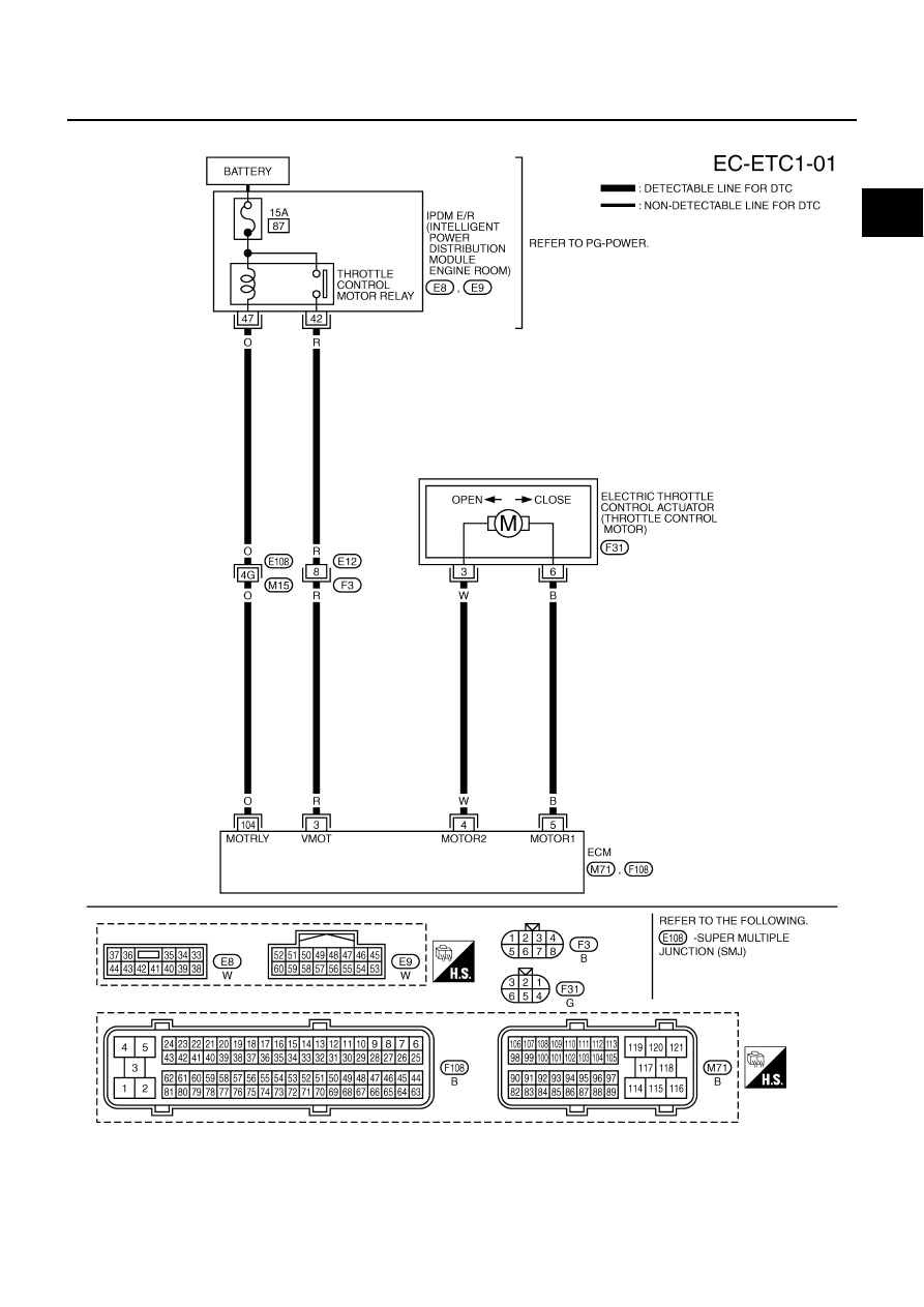
DTC P2101 ELECTRIC THROTTLE CONTROL FUNCTION
EC-605
[VQ35DE]
C
D
E
F
G
H
I
J
K
L
M
A
EC
Wiring Diagram
NBS00566
TBWT1480E
|
|
|
DTC P2101 ELECTRIC THROTTLE CONTROL FUNCTION EC-605 [VQ35DE] C D E F G H I J K L M A EC Wiring Diagram NBS00566 TBWT1480E |