Infiniti M35/M45 Y50. Manual - part 525


  Index      Infiniti     Infiniti M35/M45 Y50 - service repair manual 2007 year


Search            copyright infringement  


Content   ..  523  524  525  526   ..


Infiniti M35/M45 Y50. Manual - part 525


DTC P1572 ICC BRAKE SWITCH

EC-573

[VQ35DE]

C

D

E

F

G

H

I

J

K

L

M

A

EC

9. 

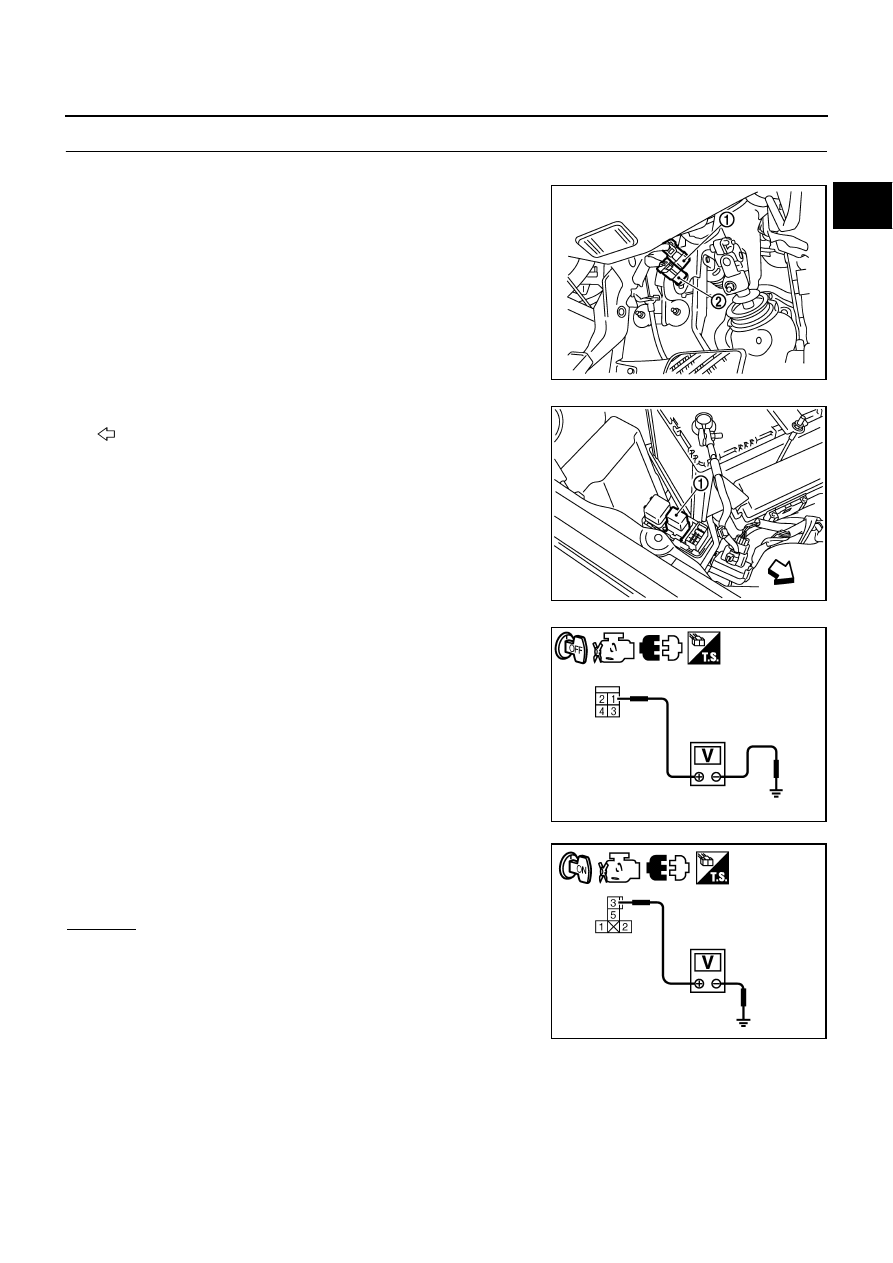
CHECK STOP LAMP SWITCH POWER SUPPLY CIRCUIT

1.

Turn ignition switch OFF.

2.

Disconnect stop lamp switch (1) harness connector.

ICC brake switch (2)

3.

Disconnect ICC brake hold relay (1) harness connector.

: Vehicle front

4.

Check voltage between stop lamp switch terminal 1 and ground
with CONSULT -II or tester.

5.

Check voltage between ICC brake hold relay terminal 3 and
ground with CONSULT -II or tester.

OK or NG

OK

>> GO TO 11.

NG

>> GO TO 10.

PBIB2705E

PBIB2699E

Voltage: Battery voltage

PBIA9488J

Voltage: Battery voltage

PBIB2740E

EC-574

[VQ35DE]

DTC P1572 ICC BRAKE SWITCH

10. 

DETECT MALFUNCTIONING PART

Check the following.

Fuse block (J/B) connector E101

10A fuse

Harness for open or short between battery and stop lamp switch

Harness for open or short between battery and ICC brake hold relay

>> Repair open circuit or short to ground or short to power in harness or connectors.

11. 

CHECK STOP LAMP SWITCH INPUT SIGNAL CIRCUIT FOR OPEN AND SHORT

1.

Disconnect ECM harness connector.

2.

Check harness continuity between the following;
ECM terminal 101 and stop lamp switch terminal 2, 
ECM terminal 101 and ICC brake hold relay terminal 5.
Refer to Wiring Diagram.

3.

Also check harness for short to ground and short to power.

OK or NG

OK

>> GO TO 13.

NG

>> GO TO 12.

12. 

DETECT MALFUNCTIONING PART

Check the following.

Harness connectors E108, M15

Harness for open or short between ECM and stop lamp switch

Harness for open or short between ECM and ICC brake hold relay

>> Repair open circuit or short to ground or short to power in harness or connectors.

13. 

CHECK STOP LAMP SWITCH

Refer to 

EC-575, "Component Inspection"

 .

OK or NG

OK

>> GO TO 14.

NG

>> Replace stop lamp switch.

14. 

CHECK ICC BRAKE HOLD RELAY

Refer to 

EC-575, "Component Inspection"

 .

OK

>> GO TO 15.

NG

>> Replace ICC brake hold relay.

15. 

CHECK INTERMITTENT INCIDENT

Refer to 

EC-153, "TROUBLE DIAGNOSIS FOR INTERMITTENT INCIDENT"

 .

>> INSPECTION END

Continuity should exist.

DTC P1572 ICC BRAKE SWITCH

EC-575

[VQ35DE]

C

D

E

F

G

H

I

J

K

L

M

A

EC

Component Inspection

NBS00556

ICC BRAKE SWITCH

1.

Turn ignition switch OFF.

2.

Disconnect ICC brake switch harness connector.

3.

Check continuity between ICC brake switch terminals 1 and 2
under the following conditions.

4.

If NG, adjust ICC brake switch installation, refer to 

BR-6,

"BRAKE PEDAL"

 , and perform step 3 again.

STOP LAMP SWITCH

1.

Turn ignition switch OFF.

2.

Disconnect stop lamp switch harness connector.

3.

Check continuity between stop lamp switch terminals 1 and 2
under the following conditions.

4.

If NG, adjust stop lamp switch installation, refer to 

BR-6,

"BRAKE PEDAL"

 , and perform step 3 again.

ICC BRAKE HOLD RELAY

1.

Check continuity between ICC brake hold relay terminals 3 and
5 under the following conditions.

2.

If NG, replace ICC brake hold relay.

Condition

Continuity

Brake pedal: Fully released

Should exist

Brake pedal: Slightly depressed

Should not exist

PBIB1536E

Condition

Continuity

Brake pedal: Fully released

Should not exist

Brake pedal: Slightly depressed

Should exist

PBIA9489J

Condition

Continuity

12V direct current supply between terminals 
1 and 2

Should not exist

No current supply

Should exist

PBIB0098E

EC-576

[VQ35DE]

DTC P1572 ASCD BRAKE SWITCH

DTC P1572 ASCD BRAKE SWITCH

PFP:25320

Component Description

NBS00557

When the brake pedal is depressed, ASCD brake switch (2) is
turned OFF and stop lamp switch (1) is turned ON. ECM detects the
state of the brake pedal by this input of two kinds (ON/OFF signal).
Refer to 

EC-36, "AUTOMATIC SPEED CONTROL DEVICE (ASCD)"

for the ASCD function.

CONSULT-II Reference Value in Data Monitor Mode

NBS00558

Specification data are reference values.

On Board Diagnosis Logic

NBS00559

This self-diagnosis has the one trip detection logic.
The MIL will not light up for this diagnosis.

NOTE:

If DTC P1572 is displayed with DTC P0605, first perform the trouble diagnosis for DTC P0605.
Refer to 

EC-483, "DTC P0605 ECM"

 .

This self-diagnosis has the one trip detection logic. When malfunction A is detected, DTC is not
stored in ECM memory. And in that case, 1st trip DTC and 1st trip freeze frame data are displayed.
1st trip DTC is erased when ignition switch OFF. And even when malfunction A is detected in two
consecutive trips, DTC is not stored in ECM memory.

PBIB2705E

MONITOR ITEM

CONDITION

SPECIFICATION

BRAKE SW1
(ASCD brake switch)

Ignition switch: ON

Brake pedal: Fully released

ON

Brake pedal: Slightly depressed

OFF

BRAKE SW2
(Stop lamp switch)

Ignition switch: ON

Brake pedal: Fully released

OFF

Brake pedal: Slightly depressed

ON

DTC No.

Trouble diagnosis 

name

DTC detecting condition

Possible cause

P1572
1572

ASCD brake 
switch

A)

When the vehicle speed is above 30 km/h 
(19 MPH), ON signals from the stop lamp 
switch and the ASCD brake switch are 
sent to the ECM at the same time.

Harness or connectors
(The stop lamp switch circuit is shorted.)

Harness or connectors
(The ASCD brake switch circuit is shorted.)

Stop lamp switch

ASCD brake switch

Incorrect stop lamp switch installation

Incorrect ASCD brake switch installation

ECM

B)

ASCD brake switch signal is not sent to 
ECM for extremely long time while the 
vehicle is driving.


Content   ..  523  524  525  526   ..