Infiniti M35/M45 Y50. Manual - part 522
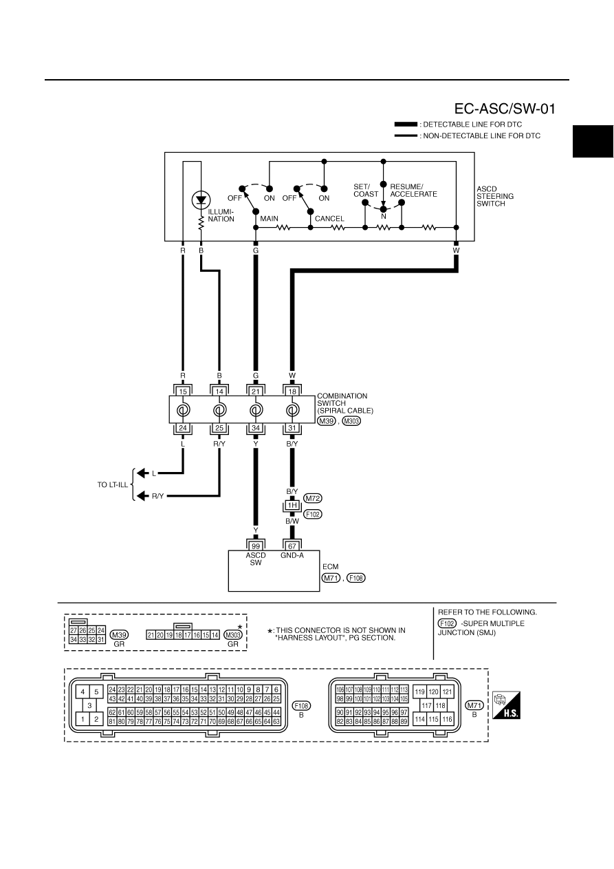
DTC P1564 ASCD STEERING SWITCH
EC-561
[VQ35DE]
C
D
E
F
G
H
I
J
K
L
M
A
EC
Wiring Diagram
NBS0054U
TBWT0981E
|
|
|
DTC P1564 ASCD STEERING SWITCH EC-561 [VQ35DE] C D E F G H I J K L M A EC Wiring Diagram NBS0054U TBWT0981E |