Infiniti M35/M45 Y50. Manual - part 514
DTC P1550 BATTERY CURRENT SENSOR
EC-529
[VQ35DE]
C
D
E
F
G
H
I
J
K
L
M
A
EC
6.
CHECK BATTERY CURRENT SENSOR INPUT SIGNAL CIRCUIT FOR OPEN AND SHORT
1.
Check harness continuity between battery current sensor terminal 3 and ECM terminal 71.
Refer to Wiring Diagram.
2.
Also check harness for short to ground and short to power.
OK or NG
OK
>> GO TO 8.
NG
>> GO TO 7.
7.
DETECT MALFUNCTIONING PART
Check the following.
●
Harness connectors E10, F1
●
Harness for open or short between battery current sensor and ECM
>> Repair open circuit or short to ground or short to power in harness or connectors.
8.
CHECK BATTERY CURRENT SENSOR
Refer to
EC-529, "Component Inspection"
OK or NG
OK
>> GO TO 9.
NG
>> Replace battery negative cable assembly.
9.
CHECK INTERMITTENT INCIDENT
Refer to
EC-153, "TROUBLE DIAGNOSIS FOR INTERMITTENT INCIDENT"
>> INSPECTION END
Component Inspection
NBS0053X
BATTERY CURRENT SENSOR
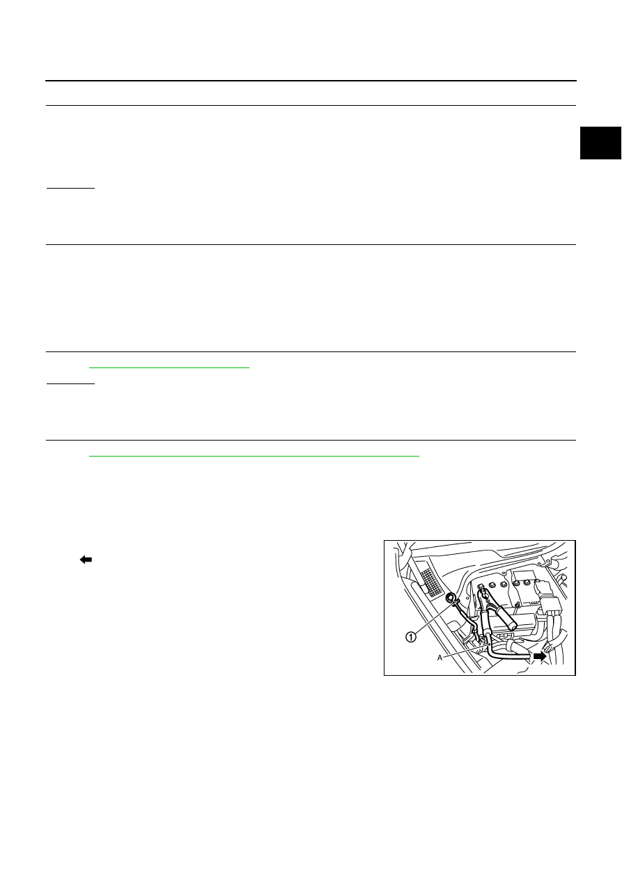
1.
Reconnect harness connectors disconnected.
2.
Disconnect battery negative cable (1).
●
: To body ground
3.
Install jumper cable (A) between battery negative terminal and
body ground.
4.
Turn ignition switch ON.
Continuity should exist.
PBIB2724E