Infiniti M35/M45 Y50. Manual - part 501


  Index      Infiniti     Infiniti M35/M45 Y50 - service repair manual 2007 year


Search            copyright infringement  


Content   ..  499  500  501  502   ..


Infiniti M35/M45 Y50. Manual - part 501


DTC P0550 PSP SENSOR

EC-477

[VQ35DE]

C

D

E

F

G

H

I

J

K

L

M

A

EC

2. 

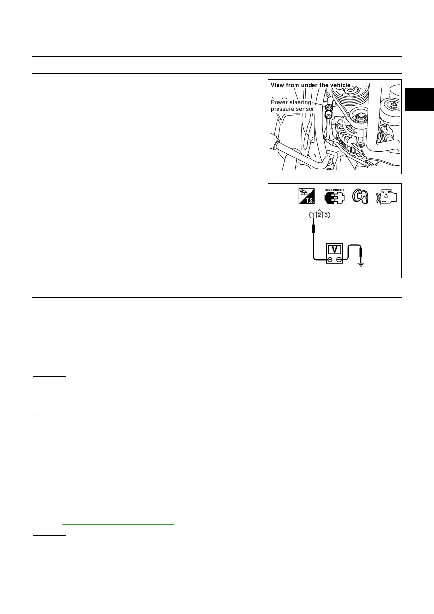
CHECK PSP SENSOR POWER SUPPLY CIRCUIT

1.

Disconnect power steering pressure (PSP) sensor harness con-
nector.

2.

Turn ignition switch ON.

3.

Check voltage between PSP sensor terminal 1 and ground with
CONSULT-II or tester.

OK or NG

OK

>> GO TO 3.

NG

>> Repair open circuit or short to ground or short to power

in harness or connectors.

3. 

CHECK PSP SENSOR GROUND CIRCUIT FOR OPEN AND SHORT

1.

Turn ignition switch OFF.

2.

Disconnect ECM harness connector.

3.

Check harness continuity between PSP sensor terminal 3 and ECM terminal 67.
Refer to Wiring Diagram.

4.

Also check harness for short to ground and short to power.

OK or NG

OK

>> GO TO 4.

NG

>> Repair open circuit or short to ground short to power in harness or connectors.

4. 

CHECK PSP SENSOR INPUT SIGNAL CIRCUIT FOR OPEN AND SHORT

1.

Check harness continuity between ECM terminal 12 and PSP sensor terminal 2.
Refer to Wiring Diagram.

2.

Also check harness for short to ground and short to power.

OK or NG

OK

>> GO TO 5.

NG

>> Repair open circuit or short to ground or short to power in harness or connectors.

5. 

CHECK PSP SENSOR

Refer to 

EC-478, "Component Inspection"

 .

OK or NG

OK

>> GO TO 6.

NG

>> Replace PSP sensor.

PBIB1579E

Voltage: Approximately 5V

PBIB0188E

Continuity should exist.

Continuity should exist.

EC-478

[VQ35DE]

DTC P0550 PSP SENSOR

6. 

CHECK INTERMITTENT INCIDENT

Refer to 

EC-153, "TROUBLE DIAGNOSIS FOR INTERMITTENT INCIDENT"

 .

>> INSPECTION END

Component Inspection

NBS00527

POWER STEERING PRESSURE SENSOR

1.

Reconnect all harness connectors disconnected.

2.

Start engine and let it idle.

3.

Check voltage between ECM terminal 12 and ground under the
following conditions.

Removal and Installation

NBS00528

POWER STEERING PRESSURE SENSOR

Refer to 

PS-39, "HYDRAULIC LINE"

 .

Condition

Voltage

Steering wheel: Being turned.

0.5 - 4.5V

Steering wheel: Not being turned.

0.4 - 0.8V

MBIB0126E

DTC P0603 ECM POWER SUPPLY

EC-479

[VQ35DE]

C

D

E

F

G

H

I

J

K

L

M

A

EC

DTC P0603 ECM POWER SUPPLY

PFP:23710

Component Description

NBS00529

Battery voltage is supplied to the ECM even when the ignition switch
is turned OFF for the ECM memory function of the DTC memory, the
air-fuel ratio feedback compensation value memory, the idle air vol-
ume learning value memory, etc.

On Board Diagnosis Logic

NBS0052A

DTC Confirmation Procedure

NBS0052B

NOTE:
If DTC Confirmation Procedure has been previously conducted, always turn ignition switch OFF and wait at
least 10 seconds before conducting the next test.

 WITH CONSULT-II

1.

Turn ignition switch ON and wait at least 1 second.

2.

Select “DATA MONITOR” mode with CONSULT-II.

3.

Start engine and let it idle for 1 second.

4.

Turn ignition switch OFF, wait at least 10 seconds, and then turn
ON.

5.

Repeat steps 3 and 4 for four times.

6.

If 1st trip DTC is detected, go to 

EC-481, "Diagnostic Procedure"

.

 WITH GST

Follow the procedure “WITH CONSULT-II” above.

PBIB1164E

DTC No.

Trouble diagnosis name

DTC detecting condition

Possible cause

P0603
0603

ECM power supply cir-
cuit

ECM back-up RAM system does not function 
properly.

Harness or connectors
[ECM power supply (back-up) circuit is 
open or shorted.]

ECM

SEF058Y

EC-480

[VQ35DE]

DTC P0603 ECM POWER SUPPLY

Wiring Diagram

NBS0052C

TBWT0970E


Content   ..  499  500  501  502   ..