Infiniti M35/M45 Y50. Manual - part 494


  Index      Infiniti     Infiniti M35/M45 Y50 - service repair manual 2007 year


Search            copyright infringement  


Content   ..  492  493  494  495   ..


Infiniti M35/M45 Y50. Manual - part 494


DTC P0455 EVAP CONTROL SYSTEM

EC-449

[VQ35DE]

C

D

E

F

G

H

I

J

K

L

M

A

EC

8. 

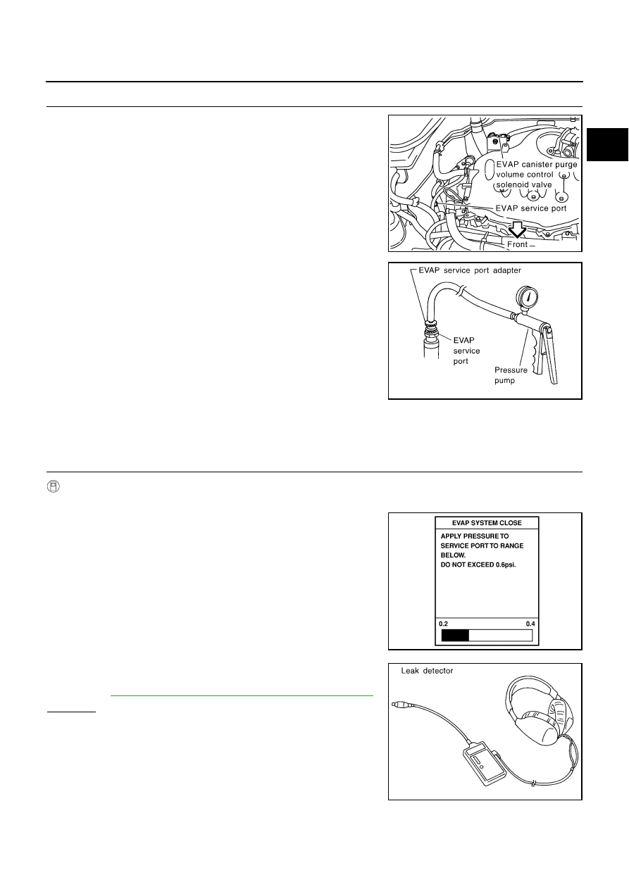
INSTALL THE PRESSURE PUMP

To locate the EVAP leak, install EVAP service port adapter and pres-
sure pump to EVAP service port securely.

NOTE:
Improper installation of the EVAP service port adapter to the
EVAP service port may cause leaking.

With CONSULT-II>>GO TO 9.
Without CONSULT-II>>GO TO 10.

9. 

CHECK FOR EVAP LEAK

 With CONSULT-II

1.

Turn ignition switch ON.

2.

Select “EVAP SYSTEM CLOSE” of “WORK SUPPORT” mode
with CONSULT-II.

3.

Touch “START” and apply pressure into the EVAP line until the
pressure indicator reaches the middle of the bar graph.

CAUTION:

Do not use compressed air or a high pressure pump.

Do not exceed 4.12 kPa (0.042 kg/cm

2

 , 0.6 psi) of pres-

sure in the system.

4.

Using EVAP leak detector, locate the EVAP leak. For the leak
detector, refer to the instruction manual for more details.
Refer to 

EC-40, "EVAPORATIVE EMISSION LINE DRAWING"

 .

OK or NG

OK

>> GO TO 11.

NG

>> Repair or replace.

PBIB2006E

SEF916U

PEF917U

SEF200U

EC-450

[VQ35DE]

DTC P0455 EVAP CONTROL SYSTEM

10. 

CHECK FOR EVAP LEAK

 Without CONSULT-II

1.

Turn ignition switch OFF.

2.

Apply 12 volts DC to EVAP canister vent control valve (1). The
valve will close. (Continue to apply 12 volts until the end of test.)

Illustration shows the view from under the vehicle

: Vehicle front

EVAP canister (2)

EVAP control system pressure sensor (3)

3.

Pressurize the EVAP line using pressure pump with 1.3 to 2.7
kPa (10 to 20 mmHg, 0.39 to 0.79 inHg), then remove pump and
EVAP service port adapter.

CAUTION:

Do not use compressed air or a high pressure pump.

Do not exceed 4.12 kPa (0.042 kg/cm

2

 , 0.6 psi) of pressure in the system.

4.

Using EVAP leak detector, locate the EVAP leak. For the leak
detector, refer to the instruction manual for more details. Refer
to 

EC-40, "EVAPORATIVE EMISSION LINE DRAWING"

 .

OK or NG

OK

>> GO TO 12.

NG

>> Repair or replace.

11. 

CHECK EVAP CANISTER PURGE VOLUME CONTROL SOLENOID VALVE OPERATION

 With CONSULT-II

1.

Disconnect vacuum hose to EVAP canister purge volume control solenoid valve at EVAP service port.

2.

Start engine.

3.

Perform “PURG VOL CONT/V” in “ACTIVE TEST” mode.

4.

Touch “Qu” on CONSULT-II screen to increase “PURG VOL
CONT/V” opening to 100%.

5.

Check vacuum hose for vacuum when revving engine up to
2,000 rpm.

OK or NG

OK

>> GO TO 14.

NG

>> GO TO 13.

PBIB2702E

SEF200U

PBIB1678E

DTC P0455 EVAP CONTROL SYSTEM

EC-451

[VQ35DE]

C

D

E

F

G

H

I

J

K

L

M

A

EC

12. 

CHECK EVAP CANISTER PURGE VOLUME CONTROL SOLENOID VALVE OPERATION

 Without CONSULT-II

1.

Start engine and warm it up to normal operating temperature.

2.

Stop engine.

3.

Disconnect vacuum hose to EVAP canister purge volume control solenoid valve at EVAP service port.

4.

Start engine and let it idle for at least 80 seconds.

5.

Check vacuum hose for vacuum when revving engine up to 2,000 rpm.

OK or NG

OK

>> GO TO 15.

NG

>> GO TO 13.

13. 

CHECK VACUUM HOSE

Check vacuum hoses for clogging or disconnection. Refer to 

EC-111, "Vacuum Hose Drawing"

 .

OK or NG

OK (With CONSULT-II)>>GO TO 14.
OK (Without CONSULT-II)>>GO TO 15.
NG

>> Repair or reconnect the hose.

14. 

CHECK EVAP CANISTER PURGE VOLUME CONTROL SOLENOID VALVE

 With CONSULT-II

1.

Start engine.

2.

Perform “PURG VOL CONT/V” in “ACTIVE TEST” mode with
CONSULT-II. Check that engine speed varies according to the
valve opening.

OK or NG

OK

>> GO TO 16.

NG

>> GO TO 15.

15. 

CHECK EVAP CANISTER PURGE VOLUME CONTROL SOLENOID VALVE

Refer to 

EC-407, "Component Inspection"

 .

OK or NG

OK

>> GO TO 16.

NG

>> Replace EVAP canister purge volume control solenoid valve.

16. 

CHECK FUEL TANK TEMPERATURE SENSOR

Refer to 

EC-336, "Component Inspection"

 .

OK or NG

OK

>> GO TO 17.

NG

>> Replace fuel level sensor unit.

Vacuum should exist.

PBIB1678E

EC-452

[VQ35DE]

DTC P0455 EVAP CONTROL SYSTEM

17. 

CHECK EVAP CONTROL SYSTEM PRESSURE SENSOR

Refer to 

EC-430, "Component Inspection"

 .

OK or NG

OK

>> GO TO 18.

NG

>> Replace EVAP control system pressure sensor.

18. 

CHECK EVAP/ORVR LINE

Check EVAP/ORVR line between EVAP canister and fuel tank for clogging, kink, looseness and improper con-
nection. For location, refer to 

EC-46, "ON BOARD REFUELING VAPOR RECOVERY (ORVR)"

 .

OK or NG

OK

>> GO TO 19.

NG

>> Repair or replace hoses and tubes.

19. 

CHECK RECIRCULATION LINE

Check recirculation line between filler neck tube and fuel tank for clogging, kink, cracks, looseness and
improper connection.

OK or NG

OK

>> GO TO 20.

NG

>> Repair or replace hose, tube or filler neck tube.

20. 

CHECK REFUELING EVAP VAPOR CUT VALVE

Refer to 

EC-49, "Component Inspection"

 .

OK or NG

OK

>> GO TO 21.

NG

>> Replace refueling EVAP vapor cut valve with fuel tank. 

21. 

CHECK INTERMITTENT INCIDENT

Refer to 

EC-153, "TROUBLE DIAGNOSIS FOR INTERMITTENT INCIDENT"

 .

>> INSPECTION END


Content   ..  492  493  494  495   ..