Infiniti M35/M45 Y50. Manual - part 491


  Index      Infiniti     Infiniti M35/M45 Y50 - service repair manual 2007 year


Search            copyright infringement  


Content   ..  489  490  491  492   ..


Infiniti M35/M45 Y50. Manual - part 491


DTC P0453 EVAP CONTROL SYSTEM PRESSURE SENSOR

EC-437

[VQ35DE]

C

D

E

F

G

H

I

J

K

L

M

A

EC

DTC P0453 EVAP CONTROL SYSTEM PRESSURE SENSOR

PFP:25085

Component Description

NBS0050V

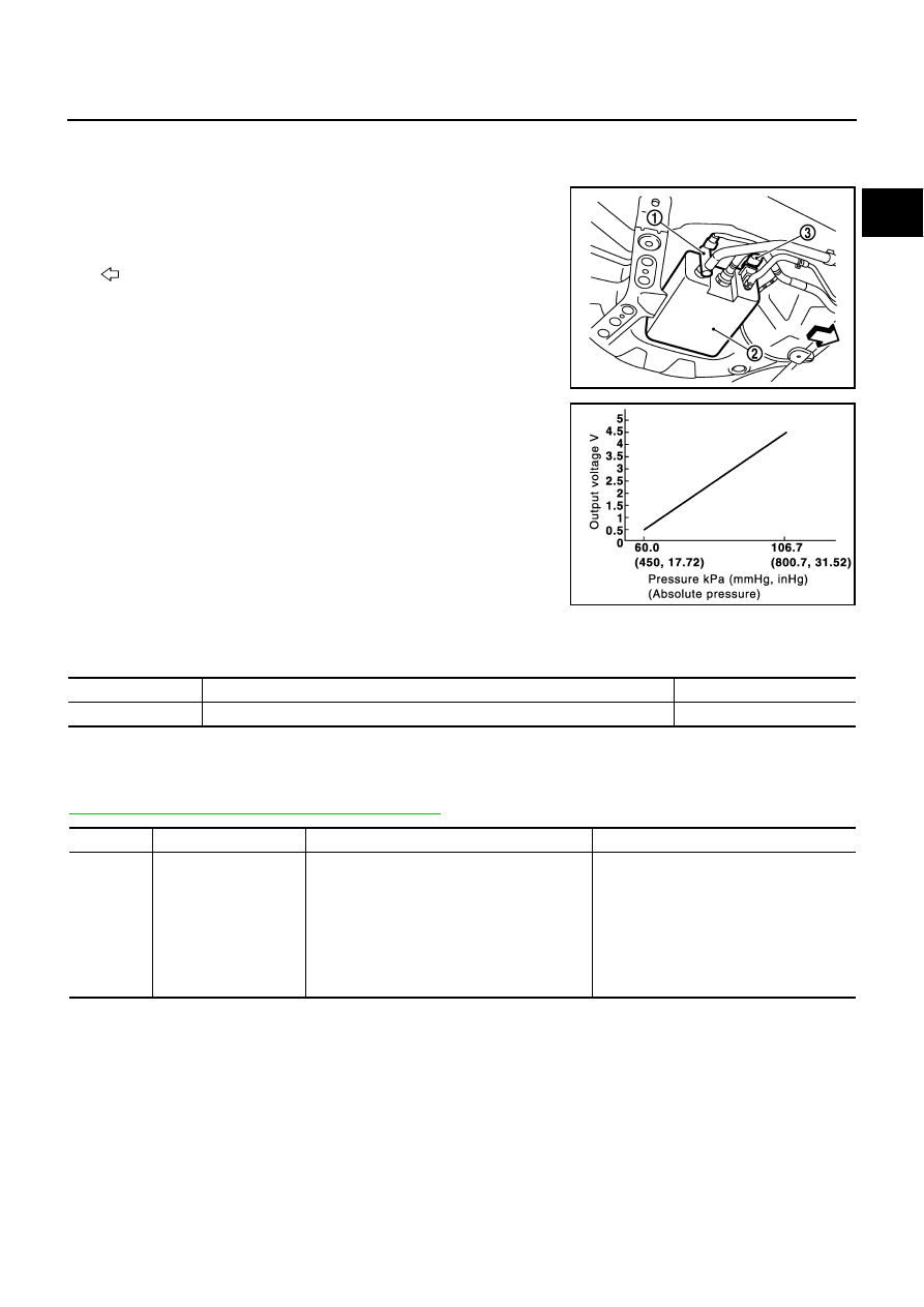
The EVAP control system pressure sensor (3) detects pressure in
the purge line. The sensor output voltage to the ECM increases as
pressure increases.

Illustration shows the view from under the vehicle.

: Vehicle front

EVAP canister vent control valve (1)

EVAP canister (2)

CONSULT-II Reference Value in Data Monitor Mode

NBS0050W

Specification data are reference values.

On Board Diagnosis Logic

NBS0050X

NOTE:
If DTC P0453 is displayed with DTC P0643, first perform the trouble diagnosis for DTC P0643. Refer to

EC-486, "DTC P0643 SENSOR POWER SUPPLY"

 .

PBIB2702E

PBIB1207E

MONITOR ITEM

CONDITION

SPECIFICATION

EVAP SYS PRES

Ignition switch: ON

Approx. 1.8 - 4.8V

DTC No.

Trouble diagnosis name

DTC detecting condition

Possible cause

P0453
0453

EVAP control system 
pressure sensor high 
input

An excessively high voltage from the sensor is 
sent to ECM.

Harness or connectors
(The sensor circuit is open or shorted.)

EVAP control system pressure sensor

EVAP canister vent control valve

EVAP canister

Rubber hose from EVAP canister vent 
control valve to vehicle frame

EC-438

[VQ35DE]

DTC P0453 EVAP CONTROL SYSTEM PRESSURE SENSOR

DTC Confirmation Procedure

NBS0050Y

NOTE:
If DTC Confirmation Procedure has been previously conducted, always turn ignition switch OFF and wait at
least 10 seconds before conducting the next test.
TESTING CONDITION:
Always perform test at a temperature of 5

°

C (41

°

F) or more.

 WITH CONSULT-II

1.

Start engine and warm it up to normal operating temperature.

2.

Turn ignition switch OFF and wait at least 10 seconds.

3.

Turn ignition switch ON.

4.

Select “DATA MONITOR” mode with CONSULT-II.

5.

Make sure that “FUEL T/TMP SE” is more than 0

°

C (32

°

F).

6.

Start engine and wait at least 20 seconds.

7.

If 1st trip DTC is detected, go to 

EC-440, "Diagnostic Procedure"

.

 WITH GST

1.

Start engine and warm it up to normal operating temperature.

2.

Check that voltage between ECM terminal 107 (Fuel tank tem-
perature sensor signal) and ground is less than 4.2V.

3.

Turn ignition switch OFF and wait at least 10 seconds.

4.

Start engine and wait at least 20 seconds.

5.

Select Service $07 with GST.
If 1st trip DTC is detected, go to 

EC-440, "Diagnostic Procedure"

.

SEF194Y

PBIB1110E

DTC P0453 EVAP CONTROL SYSTEM PRESSURE SENSOR

EC-439

[VQ35DE]

C

D

E

F

G

H

I

J

K

L

M

A

EC

Wiring Diagram

NBS0050Z

TBWT1476E

EC-440

[VQ35DE]

DTC P0453 EVAP CONTROL SYSTEM PRESSURE SENSOR

Specification data are reference values and are measured between each terminal and ground.

CAUTION:

Do not use ECM ground terminals when measuring input/output voltage. Doing so may result in dam-
age to the ECM's transistor. Use a ground other than ECM terminals, such as the ground.

Diagnostic Procedure

NBS00510

1. 

CHECK GROUND CONNECTIONS

1.

Turn ignition switch OFF.

2.

Loosen and retighten two ground screws on the body.
Refer to 

EC-160, "Ground Inspection"

 .

OK or NG

OK

>> GO TO 2.

NG

>> Repair or replace ground connections.

2. 

CHECK CONNECTOR

1.

Disconnect EVAP control system pressure sensor (3) harness
connector.

Illustration shows the view from under the vehicle.

: Vehicle front

EVAP canister vent control valve (1)

EVAP canister (2)

2.

Check sensor harness connector for water.

OK or NG

OK

>> GO TO 3.

NG

>> Repair or replace harness connector.

TER-

MINAL 

NO.

WIRE 

COLOR

ITEM

CONDITION

DATA (DC Voltage)

32

R/G

EVAP control system pres-
sure sensor

[Ignition switch: ON]

Approximately 1.8 - 4.8V

48

BR

Sensor power supply
(EVAP control system pres-
sure sensor)

[Ignition switch: ON]

Approximately 5V

67

B/W

Sensor ground

[Engine is running]

Warm-up condition

Idle speed

Approximately 0V

1.

Body ground M70

2.

Body ground M16

PBIB2782E

Water should not exist.

PBIB2702E


Content   ..  489  490  491  492   ..