Infiniti M35/M45 Y50. Manual - part 489


  Index      Infiniti     Infiniti M35/M45 Y50 - service repair manual 2007 year


Search            copyright infringement  


Content   ..  487  488  489  490   ..


Infiniti M35/M45 Y50. Manual - part 489


DTC P0451 EVAP CONTROL SYSTEM PRESSURE SENSOR

EC-429

[VQ35DE]

C

D

E

F

G

H

I

J

K

L

M

A

EC

DTC Confirmation Procedure

NBS0050L

NOTE:
If DTC Confirmation Procedure has been previously conducted, always turn ignition switch OFF and wait at
least 10 seconds before conducting the next test.

 WITH CONSULT-II

1.

Turn ignition switch OFF and wait at least 10 seconds.

2.

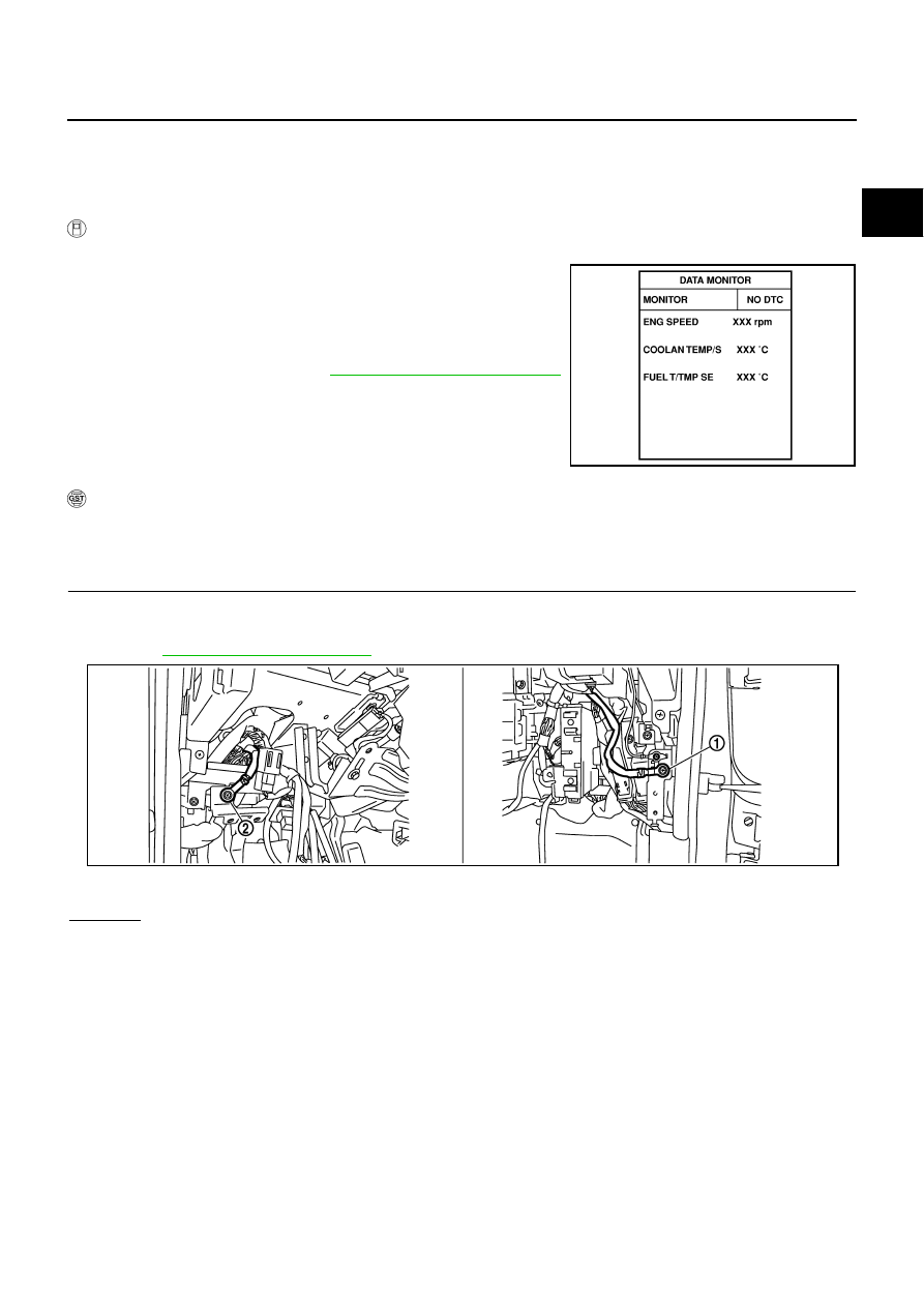
Turn ignition switch ON and select “DATA MONITOR” mode with
CONSULT-II.

3.

Start engine and wait at least 40 seconds.

NOTE:
Do not depress accelerator pedal even slightly.
If 1st trip DTC is detected, go to 

EC-429, "Diagnostic Procedure"

.

 WITH GST

Follow the procedure “WITH CONSULT-II” above.

Diagnostic Procedure

NBS0050M

1. 

CHECK GROUND CONNECTIONS

1.

Turn ignition switch OFF.

2.

Loosen and retighten two ground screws on the body.
Refer to 

EC-160, "Ground Inspection"

 .

OK or NG

OK

>> GO TO 2.

NG

>> Repair or replace ground connections.

SEF194Y

1.

Body ground M70

2.

Body ground M16

PBIB2782E

EC-430

[VQ35DE]

DTC P0451 EVAP CONTROL SYSTEM PRESSURE SENSOR

2. 

CHECK EVAP CONTROL SYSTEM PRESSURE SENSOR CONNECTOR FOR WATER

1.

Disconnect EVAP control system pressure sensor (3) harness
connector.

Illustration shows the view from under the vehicle.

: Vehicle front

EVAP canister vent control valve (1)

EVAP canister (2)

2.

Check sensor harness connector for water.

OK or NG

OK

>> GO TO 3.

NG

>> Repair or replace harness connector.

3. 

CHECK EVAP CONTROL SYSTEM PRESSURE SENSOR

Refer to 

EC-430, "Component Inspection"

 .

OK or NG

OK

>> GO TO 4.

NG

>> Replace EVAP control system pressure sensor.

4. 

CHECK INTERMITTENT INCIDENT

Refer to 

EC-153, "TROUBLE DIAGNOSIS FOR INTERMITTENT INCIDENT"

 .

For Wiring Diagram, refer to 

EC-433, "Wiring Diagram"

 .

>> INSPECTION END

Component Inspection

NBS0050N

EVAP CONTROL SYSTEM PRESSURE SENSOR

1.

Remove EVAP control system pressure sensor with its harness connector connected from EVAP canister.
Always replace O-ring with a new one.

2.

Install a vacuum pump to EVAP control system pressure sensor.

3.

Turn ignition switch ON and check output voltage between ECM
terminal 32 and ground under the following conditions.

CAUTION:

Always calibrate the vacuum pump gauge when using it.

Do not apply below -93.3 kPa (-700 mmHg, -27.56 inHg) or
pressure over 101.3 kPa (760 mmHg, 29.92 inHg).

4.

If NG, replace EVAP control system pressure sensor.

Water should not exist.

PBIB2702E

Applied vacuum kPa

(mmHg, inHg)

Voltage V

Not applied

1.8 - 4.8

-26.7 (-200, -7.87)

2.1 to 2.5V lower than above value

PBIB1173E

DTC P0452 EVAP CONTROL SYSTEM PRESSURE SENSOR

EC-431

[VQ35DE]

C

D

E

F

G

H

I

J

K

L

M

A

EC

DTC P0452 EVAP CONTROL SYSTEM PRESSURE SENSOR

PFP:25085

Component Description

NBS0050O

The EVAP control system pressure sensor (3) detects pressure in
the purge line. The sensor output voltage to the ECM increases as
pressure increases.

Illustration shows the view from under the vehicle.

: Vehicle front

EVAP canister vent control valve (1)

EVAP canister (2)

CONSULT-II Reference Value in Data Monitor Mode

NBS0050P

Specification data are reference values.

On Board Diagnosis Logic

NBS0050Q

NOTE:
If DTC P0452 is displayed with DTC P0643, first perform the trouble diagnosis for DTC P0643. Refer to

EC-486, "DTC P0643 SENSOR POWER SUPPLY"

 .

PBIB2702E

PBIB1207E

MONITOR ITEM

CONDITION

SPECIFICATION

EVAP SYS PRES

Ignition switch: ON

Approx. 1.8 - 4.8V

DTC No.

Trouble diagnosis name

DTC detecting condition

Possible cause

P0452
0452

EVAP control system 
pressure sensor low 
input

An excessively low voltage from the sensor is 
sent to ECM.

Harness or connectors
(The sensor circuit is open or shorted.)

EVAP control system pressure sensor

EC-432

[VQ35DE]

DTC P0452 EVAP CONTROL SYSTEM PRESSURE SENSOR

DTC Confirmation Procedure

NBS0050R

NOTE:
If DTC Confirmation Procedure has been previously conducted, always turn ignition switch OFF and wait at
least 10 seconds before conducting the next test.
TESTING CONDITION:
Always perform test at a temperature of 5

°

C (41

°

F) or more.

 WITH CONSULT-II

1.

Start engine and warm it up to normal operating temperature.

2.

Turn ignition switch OFF and wait at least 10 seconds.

3.

Turn ignition switch ON.

4.

Select “DATA MONITOR” mode with CONSULT-II.

5.

Make sure that “FUEL T/TMP SE” is more than 0

°

C (32

°

F).

6.

Start engine and wait at least 20 seconds.
If 1st trip DTC is detected, go to 

EC-434, "Diagnostic Procedure"

.

 WITH GST

1.

Start engine and warm it up to normal operating temperature.

2.

Check that voltage between ECM terminal 107 (Fuel tank tem-
perature sensor signal) and ground is less than 4.2V.

3.

Turn ignition switch OFF and wait at least 10 seconds.

4.

Start engine and wait at least 20 seconds.

5.

Select Service $07 with GST.
If 1st trip DTC is detected, go to 

EC-434, "Diagnostic Procedure"

.

SEF194Y

PBIB1110E


Content   ..  487  488  489  490   ..