Infiniti M35/M45 Y50. Manual - part 460
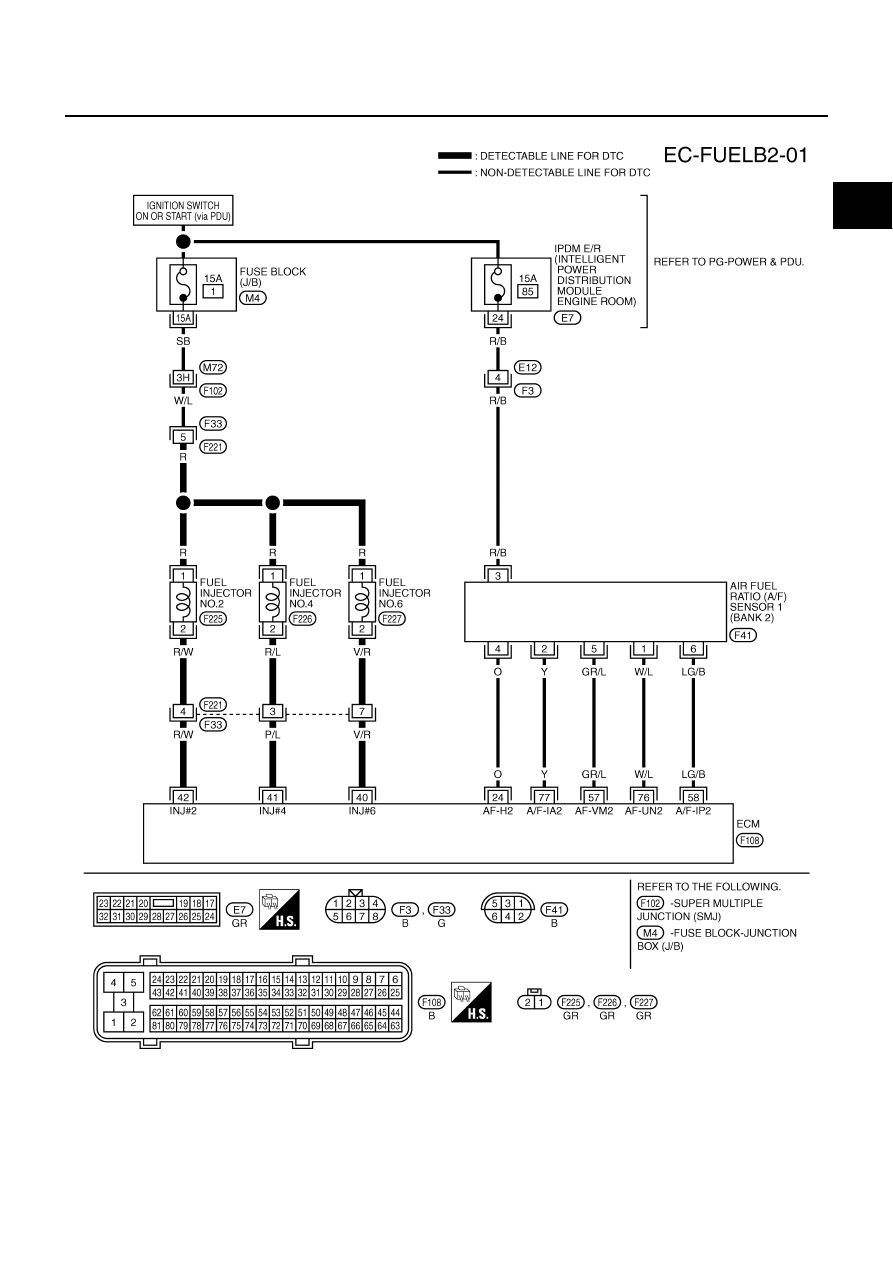
DTC P0171, P0174 FUEL INJECTION SYSTEM FUNCTION
EC-313
[VQ35DE]
C
D
E
F
G
H
I
J
K
L
M
A
EC
BANK 2
TBWT0957E
|
|
|
DTC P0171, P0174 FUEL INJECTION SYSTEM FUNCTION EC-313 [VQ35DE] C D E F G H I J K L M A EC BANK 2 TBWT0957E |