Infiniti M35/M45 Y50. Manual - part 443


  Index      Infiniti     Infiniti M35/M45 Y50 - service repair manual 2007 year


Search            copyright infringement  


Content   ..  441  442  443  444   ..


Infiniti M35/M45 Y50. Manual - part 443


DTC P0131, P0151 A/F SENSOR 1

EC-245

[VQ35DE]

C

D

E

F

G

H

I

J

K

L

M

A

EC

3.

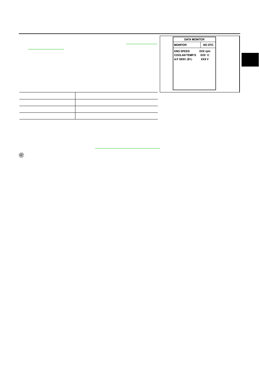
Check “A/F SEN1 (B1)” or “A/F SEN1 (B2)” indication.
If the indication is constantly approx. 0V, go to 

EC-249, "Diag-

nostic Procedure"

 .

If the indication is not constantly approx. 0V, go to next step.

4.

Turn ignition switch OFF, wait at least 10 seconds and then
restart engine.

5.

Drive and accelerate vehicle to more than 40 km/h (25 MPH)
within 20 seconds after restarting engine.

6.

Maintain the following conditions for about 20 consecutive sec-
onds.

NOTE:

Keep the accelerator pedal as steady as possible during the cruising.

If this procedure is not completed within 1 minute after restarting engine at step 4, return to step
4.

7.

If 1st trip DTC is displayed, go to 

EC-249, "Diagnostic Procedure"

 .

 WITH GST

Follow the procedure “WITH CONSULT-II” above.

ENG SPEED

1,000 - 3,200 rpm

VHCL SPEED SE

More than 40 km/h (25 MPH)

B/FUEL SCHDL

1.5 - 9.0 msec

Selector lever

Suitable position

SEF581Z

EC-246

[VQ35DE]

DTC P0131, P0151 A/F SENSOR 1

Wiring Diagram

NBS004WK

BANK 1

TBWT0979E

DTC P0131, P0151 A/F SENSOR 1

EC-247

[VQ35DE]

C

D

E

F

G

H

I

J

K

L

M

A

EC

Specification data are reference values and are measured between each terminal and ground.
Pulse signal is measured by CONSULT-II.

CAUTION:

Do not use ECM ground terminals when measuring input/output voltage. Doing so may result in dam-
age to the ECM's transistor. Use a ground other than ECM terminals, such as the ground.

: Average voltage for pulse signal (Actual pulse signal can be confirmed by oscilloscope.)

TER-

MINAL 

NO.

WIRE 

COLOR

ITEM

CONDITION

DATA (DC Voltage)

2

SB

A/F sensor 1 heater
(bank 1)

[Engine is running]

Warm-up condition

Idle speed

Approximately 5V

16

G/W

A/F sensor 1 (bank 1)

[Engine is running]

Warm-up condition

Idle speed

Approximately 3.1V

35

BR/W

Approximately 2.6V

56

G

Approximately 2.3V

75

GR

Approximately 2.3V

PBIB1584E

EC-248

[VQ35DE]

DTC P0131, P0151 A/F SENSOR 1

BANK 2

TBWT0980E


Content   ..  441  442  443  444   ..