Infiniti M35/M45 Y50. Manual - part 438


  Index      Infiniti     Infiniti M35/M45 Y50 - service repair manual 2007 year


Search            copyright infringement  


Content   ..  436  437  438  439   ..


Infiniti M35/M45 Y50. Manual - part 438


DTC P0122, P0123 TP SENSOR

EC-225

[VQ35DE]

C

D

E

F

G

H

I

J

K

L

M

A

EC

Component Inspection

NBS004VP

THROTTLE POSITION SENSOR

1.

Reconnect all harness connectors disconnected.

2.

Perform 

EC-86, "Throttle Valve Closed Position Learning"

 .

3.

Turn ignition switch ON.

4.

Set selector lever to D position. 
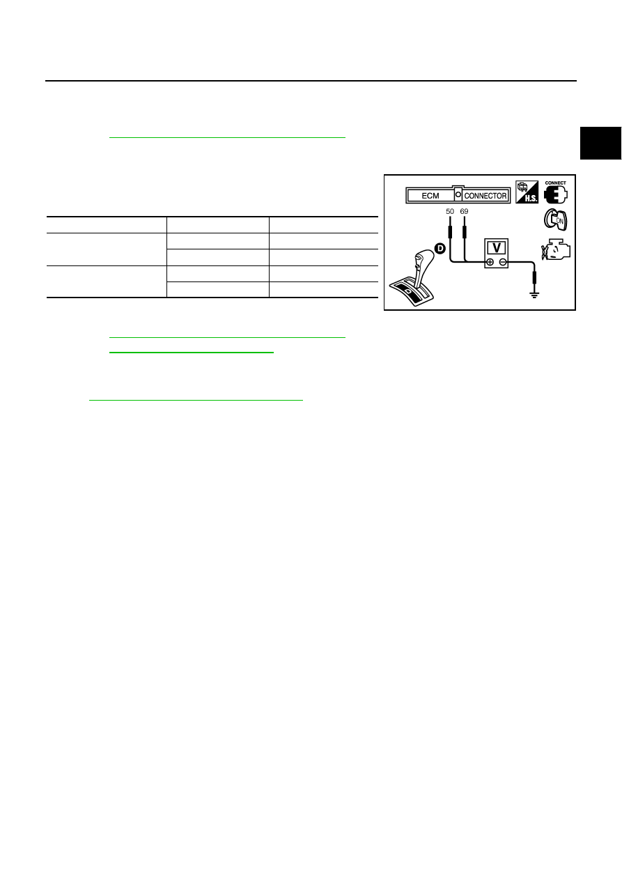
5.

Check voltage between ECM terminals 50 (TP sensor 1 signal),
69 (TP sensor 2 signal) and ground under the following condi-
tions.

6.

If NG, replace electric throttle control actuator and go to the next
step.

7.

Perform 

EC-86, "Throttle Valve Closed Position Learning"

 .

8.

Perform 

EC-86, "Idle Air Volume Learning"

 .

Removal and Installation

NBS004VQ

ELECTRIC THROTTLE CONTROL ACTUATOR

Refer to 

EM-21, "INTAKE MANIFOLD COLLECTOR"

 .

Terminal

Accelerator pedal

Voltage

50
(Throttle position sensor 1)

Fully released

More than 0.36V

Fully depressed

Less than 4.75V

69
 (Throttle position sensor 2)

Fully released

Less than 4.75V

Fully depressed

More than 0.36V

PBIB1530E

EC-226

[VQ35DE]

DTC P0125 ECT SENSOR

DTC P0125 ECT SENSOR

PFP:22630

Component Description

NBS004VR

NOTE:
If DTC P0125 is displayed with P0117 or P0118, first perform the trouble diagnosis for DTC P0117 or
P0118. Refer to 

EC-214, "DTC P0117, P0118 ECT SENSOR"

 .

The engine coolant temperature sensor is used to detect the engine
coolant temperature. The sensor modifies a voltage signal from the
ECM. The modified signal returns to the ECM as the engine coolant
temperature input. The sensor uses a thermistor which is sensitive to
the change in temperature. The electrical resistance of the ther-
mistor decreases as temperature increases.

<Reference data>

*: This data is reference value and is measured between ECM terminal 73 (Engine
coolant temperature sensor) and ground.

CAUTION:

Do not use ECM ground terminals when measuring input/output voltage. Doing so may result in dam-
age to the ECM's transistor. Use a ground other than ECM terminals, such as the ground.

On Board Diagnosis Logic

NBS004VS

SEF594K

Engine coolant 

temperature

°

C (

°

F)

Voltage*

V

Resistance

k

–10 (14)

4.4

7.0 - 11.4

20 (68)

3.5

2.1 - 2.9

50 (122)

2.2

0.68 - 1.00

90 (194)

0.9

0.236 - 0.260

SEF012P

DTC No.

Trouble diagnosis name

DTC detecting condition

Possible cause

P0125
0125

Insufficient engine cool-
ant temperature for 
closed loop fuel control

Voltage sent to ECM from the sensor is not 
practical, even when some time has passed 
after starting the engine.

Engine coolant temperature is insufficient for 
closed loop fuel control.

Harness or connectors
(High resistance in the circuit)

Engine coolant temperature sensor

Thermostat

DTC P0125 ECT SENSOR

EC-227

[VQ35DE]

C

D

E

F

G

H

I

J

K

L

M

A

EC

DTC Confirmation Procedure

NBS004VT

CAUTION:

Be careful not to overheat engine.
NOTE:
If DTC Confirmation Procedure has been previously conducted, always turn ignition switch OFF and wait at
least 10 seconds before conducting the next test.

 WITH CONSULT-II

1.

Turn ignition switch ON.

2.

Select “DATA MONITOR” mode with CONSULT-II.

3.

Check that “COOLAN TEMP/S” is above 10

°

C (50

°

F).

If it is above 10

°

C (50

°

F), the test result will be OK.

If it is below 10

°

C (50

°

F), go to following step.

4.

Start engine and run it for 65 minutes at idle speed.
If “COOLAN TEMP/S” increases to more than 10

°

C (50

°

F)

within 65 minutes, stop engine because the test result will
be OK.

5.

If 1st trip DTC is detected, go to 

EC-227, "Diagnostic Procedure"

.

 WITH GST

Follow the procedure “WITH CONSULT-II” above.

Diagnostic Procedure

NBS004VU

1. 

CHECK GROUND CONNECTIONS

1.

Turn ignition switch OFF.

2.

Loosen and retighten two ground screws on the body.
Refer to 

EC-160, "Ground Inspection"

 .

OK or NG

OK

>> GO TO 2.

NG

>> Repair or replace ground connections.

2. 

CHECK ENGINE COOLANT TEMPERATURE SENSOR

Refer to 

EC-228, "Component Inspection"

 .

OK or NG

OK

>> GO TO 3.

NG

>> Replace engine coolant temperature sensor.

SEF174Y

1.

Body ground M70

2.

Body ground M16

PBIB2782E

EC-228

[VQ35DE]

DTC P0125 ECT SENSOR

3. 

CHECK THERMOSTAT OPERATION

When the engine is cold [lower than 70

°

C (158

°

F)] condition, grasp lower radiator hose and confirm the engine

coolant does not flow.

OK or NG

OK

>> GO TO 4.

NG

>> Repair or replace thermostat. Refer to 

CO-29, "WATER INLET AND THERMOSTAT ASSEMBLY"

.

4. 

CHECK INTERMITTENT INCIDENT

Refer to 

EC-153, "TROUBLE DIAGNOSIS FOR INTERMITTENT INCIDENT"

 .

Refer to 

EC-216, "Wiring Diagram"

 .

>> INSPECTION END

Component Inspection

NBS004VV

ENGINE COOLANT TEMPERATURE SENSOR

1.

Check resistance between engine coolant temperature sensor
terminals 1 and 2 as shown in the figure.

<Reference data>

2.

If NG, replace engine coolant temperature sensor.

Removal and Installation

NBS004VW

ENGINE COOLANT TEMPERATURE SENSOR

Refer to 

CO-31, "WATER OUTLET AND WATER PIPING"

 .

PBIB2005E

Temperature

°

C (

°

F)

Resistance

k

20 (68)

2.1 - 2.9

50 (122)

0.68 - 1.00

90 (194)

0.236 - 0.260

SEF012P


Content   ..  436  437  438  439   ..