Infiniti M35/M45 Y50. Manual - part 427
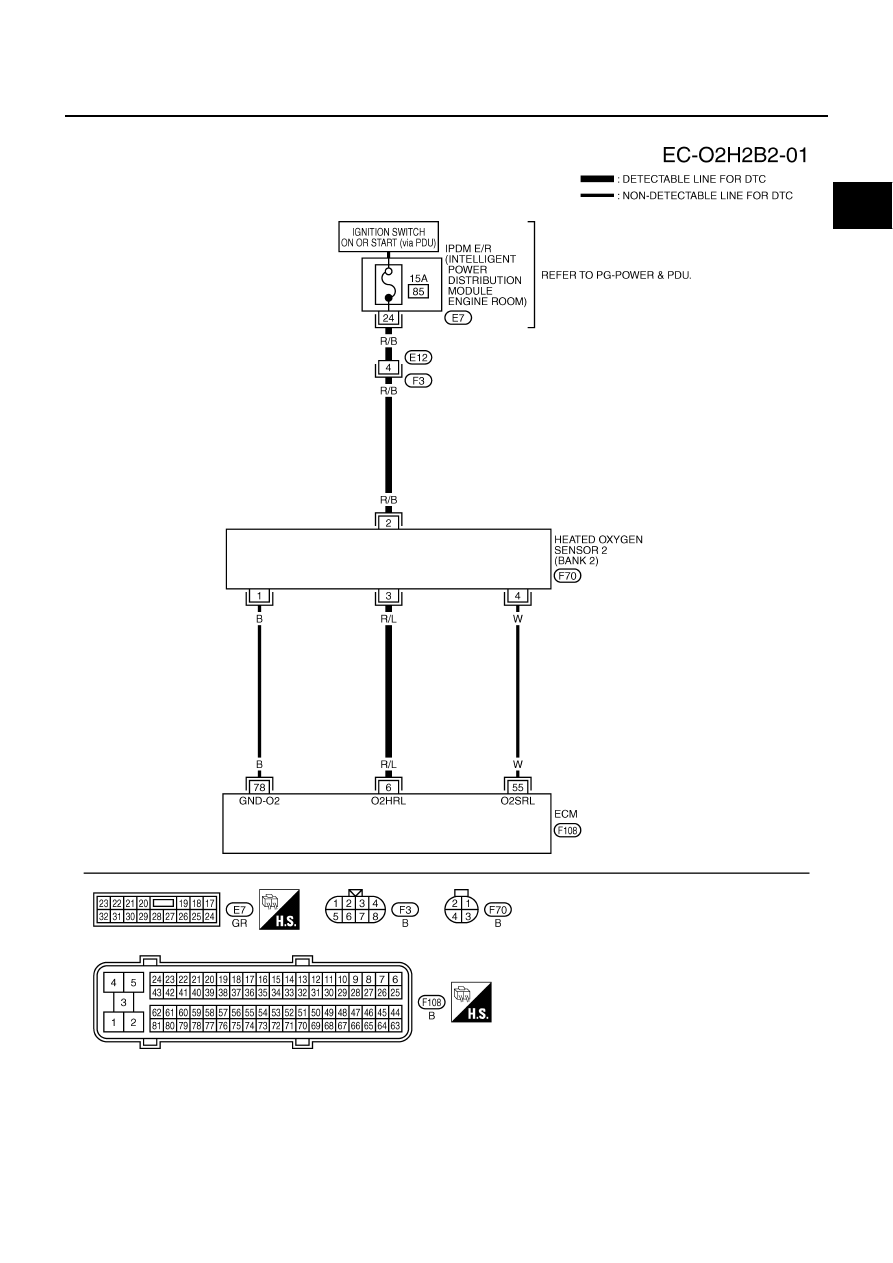
DTC P0037, P0038, P0057, P0058 HO2S2 HEATER
EC-181
[VQ35DE]
C
D
E
F
G
H
I
J
K
L
M
A
EC
BANK 2
TBWT1471E
|
|
|
DTC P0037, P0038, P0057, P0058 HO2S2 HEATER EC-181 [VQ35DE] C D E F G H I J K L M A EC BANK 2 TBWT1471E |