Infiniti M35/M45 Y50. Manual - part 401
 

  Index      Infiniti     Infiniti M35/M45 Y50 - service repair manual 2007 year


Search            copyright infringement  


Content   ..  399  400  401  402   ..


Infiniti M35/M45 Y50. Manual - part 401


ON BOARD DIAGNOSTIC (OBD) SYSTEM

EC-77

[VQ35DE]

C

D

E

F

G

H

I

J

K

L

M

A

EC

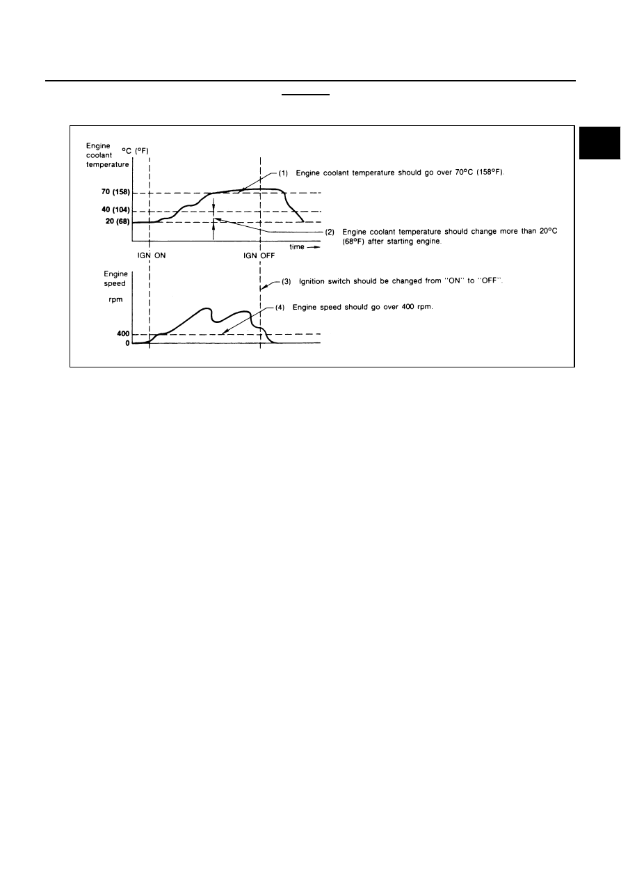
EXPLANATION FOR DRIVING PATTERNS EXCEPT  FOR “MISFIRE <EXHAUST QUALITY 
DETERIORATION>”, “FUEL INJECTION SYSTEM”
<Driving Pattern A>

The A counter will be cleared when the malfunction is detected regardless of (1) - (4).

The A counter will be counted up when (1) - (4) are satisfied without the same malfunction.

The DTC will not be displayed after the A counter reaches 40.

<Driving Pattern B>

Driving pattern B means the vehicle operation as follows:
All components and systems should be monitored at least once by the OBD system.

The B counter will be cleared when the malfunction is detected once regardless of the driving pattern.

The B counter will be counted up when driving pattern B is satisfied without any malfunctions.

The MIL will go off when the B counter reaches 3 (*2 in OBD SYSTEM OPERATION CHART).

AEC574

EC-78

[VQ35DE]

BASIC SERVICE PROCEDURE

BASIC SERVICE PROCEDURE

PFP:00018

Basic Inspection

NBS004SQ

1. 

INSPECTION START

1.

Check service records for any recent repairs that may indicate a related malfunction, or a current need for
scheduled maintenance.

2.

Open engine hood and check the following:

Harness connectors for improper connections

Wiring harness for improper connections, pinches and cut

Vacuum hoses for splits, kinks and improper connections

Hoses and ducts for leaks

Air cleaner clogging

Gasket

3.

Confirm that electrical or mechanical loads are not applied.

Headlamp switch is OFF.

Air conditioner switch is OFF.

Rear window defogger switch is OFF.

Steering wheel is in the straight-ahead position, etc.

4.

Start engine and warm it up until engine coolant temperature
indicator points the middle of gauge.
Ensure engine stays below 1,000 rpm.

5.

Run engine at about 2,000 rpm for about 2 minutes under no
load.

6.

Make sure that no DTC is displayed with CONSULT-II or GST.

OK or NG

OK

>> GO TO 3.

NG

>> GO TO 2.

2. 

REPAIR OR REPLACE

Repair or replace components as necessary according to corresponding Diagnostic Procedure.

>> GO TO 3

SEF983U

SEF976U

SEF977U

BASIC SERVICE PROCEDURE

EC-79

[VQ35DE]

C

D

E

F

G

H

I

J

K

L

M

A

EC

3. 

CHECK TARGET IDLE SPEED

 With CONSULT-II

1.

Run engine at about 2,000 rpm for about 2 minutes under no load.

2.

Rev engine (2,000 to 3,000 rpm) two or three times under no
load, then run engine at idle speed for about 1 minute.

3.

Read idle speed in “DATA MONITOR” mode with CONSULT-II.
Refer to 

EC-83, "IDLE SPEED"

 .

 Without CONSULT-II

1.

Run engine at about 2,000 rpm for about 2 minutes under no load.

2.

Rev engine (2,000 to 3,000 rpm) two or three times under no load, then run engine at idle speed for about
1 minute.

3.

Check idle speed.
Refer to 

EC-83, "IDLE SPEED"

 .

OK or NG

OK

>> GO TO 10.

NG

>> GO TO 4.

4. 

PERFORM ACCELERATOR PEDAL RELEASED POSITION LEARNING

1.

Stop engine.

2.

Perform 

EC-86, "Accelerator Pedal Released Position Learning"

 .

>> GO TO 5.

5. 

PERFORM THROTTLE VALVE CLOSED POSITION LEARNING

Perform 

EC-86, "Throttle Valve Closed Position Learning"

 .

>> GO TO 6.

PBIA8513J

650 

±

 50 rpm (in P or N position)

SEF058Y

650 

±

 50 rpm (in P or N position)

EC-80

[VQ35DE]

BASIC SERVICE PROCEDURE

6. 

PERFORM IDLE AIR VOLUME LEARNING

Refer to 

EC-86, "Idle Air Volume Learning"

 .

Is Idle Air Volume Learning carried out successfully?

Yes or No

Yes

>> GO TO 7.

No

>> 1. Follow the instruction of Idle Air Volume Learning.

2. GO TO 4.

7. 

CHECK TARGET IDLE SPEED AGAIN

 With CONSULT-II

1.

Start engine and warm it up to normal operating temperature.

2.

Read idle speed in “DATA MONITOR” mode with CONSULT-II.
Refer to 

EC-83, "IDLE SPEED"

 .

 Without CONSULT-II

1.

Start engine and warm it up to normal operating temperature.

2.

Check idle speed.
Refer to 

EC-83, "IDLE SPEED"

 .

OK or NG

OK

>> GO TO 10.

NG

>> GO TO 8.

8. 

DETECT MALFUNCTIONING PART

Check the Following.

Check camshaft position sensor (PHASE) and circuit. Refer to 

EC-371, "DTC P0340, P0345 CMP SEN-

SOR (PHASE)"

 .

Check crankshaft position sensor (POS) and circuit. Refer to 

EC-364, "DTC P0335 CKP SENSOR (POS)"

.

OK or NG

OK

>> GO TO 9.

NG

>> 1. Repair or replace.

2. GO TO 4.

9. 

CHECK ECM FUNCTION

1.

Substitute another known-good ECM to check ECM function. (ECM may be the cause of an incident, but
this is a rare case.)

2.

Perform initialization of IVIS (NATS) system and registration of all IVIS (NATS) ignition key IDs. Refer to

BL-248, "ECM Re-Communicating Function"

 .

>> GO TO 4.

650 

±

 50 rpm (in P or N position)

SEF174Y

650 

±

 50 rpm (in P or N position)


Content   ..  399  400  401  402   ..