Infiniti M35/M45 Y50. Manual - part 353
WATER PUMP
CO-53
[VK45DE]
C
D
E
F
G
H
I
J
K
L
M
A
CO
WATER PUMP
PFP:21020
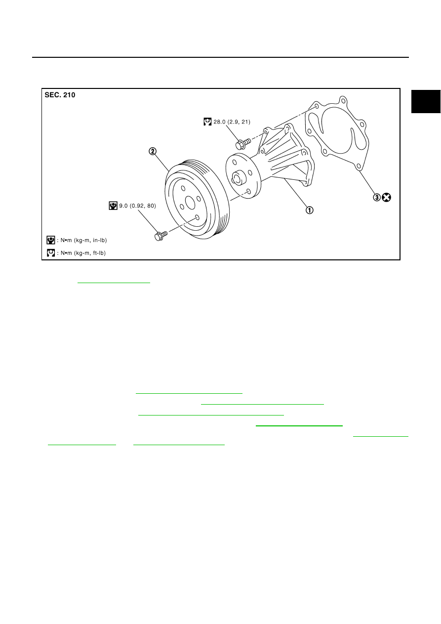
Components
NBS004RP
●
Refer to
Removal and Installation
NBS004RQ
CAUTION:
●
When removing water pump, be careful not to get engine coolant on drive belts.
●
Water pump can not be disassembled and should be replaced as a unit.
●
After installing water pump, connect hose and clamp securely, then check for leaks using radiator
cap tester (commercial service tool) and radiator cap tester adapter (commercial service tool).
REMOVAL
1.
Remove following parts:
●
Front engine undercover (power tool)
●
Engine cover: Refer to
●
Engine room cover (RH and LH): Refer to
●
Air duct (inlet): Refer to
EM-177, "AIR CLEANER AND AIR DUCT"
●
Alternator, water pump and A/C compressor belt: Refer to
2.
Drain engine coolant from drain plugs on radiator and both side of cylinder block. Refer to
CAUTION:
●
Perform this step when engine is cold.
●
Do not spill engine coolant on drive belts.
3.
Remove water pump pulley.
4.
Remove water pump.
●
Engine coolant will leak from cylinder block, so have a receptacle ready under vehicle.
CAUTION:
●
Handle the water pump vane so that it does not contact any other parts.
●
Do not disassemble water pump.
1.
Water pump
2.
Water pump pulley
3.
Gasket
PBIC3396E