Infiniti M35/M45 Y50. Manual - part 343


  Index      Infiniti     Infiniti M35/M45 Y50 - service repair manual 2007 year


Search            copyright infringement  


Content   ..  341  342  343  344   ..


Infiniti M35/M45 Y50. Manual - part 343


ENGINE COOLANT

CO-13

[VQ35DE]

C

D

E

F

G

H

I

J

K

L

M

A

CO

7.

Stop the engine and cool down to less than approximately 50

°

C (122

°

F).

Cool down using fan to reduce the time.

If necessary, refill radiator up to filler neck with engine coolant.

8.

Refill reservoir tank to “MAX” level line with engine coolant.

9.

Repeat steps 4 through 7 two or more times with radiator cap installed until engine coolant level no longer
drops. 

10. Check cooling system for leaks with engine running.

11. Warm up the engine, and check for sound of engine coolant flow while running engine from idle up to

3,000 rpm with heater temperature controller set at several position between “COOL” and “WARM”.

Sound may be noticeable at heater unit.

12. Repeat step 11 three times.

13. If sound is heard, bleed air from cooling system by repeating step 4 through 7 until engine coolant level no

longer drops. 

FLUSHING COOLING SYSTEM

1.

Install reservoir tank if removed, and radiator drain plug.

CAUTION:

Be sure to clean drain plug and install with new O-ring.

If water drain plugs on cylinder block are removed, close and tighten them. Refer to 

EM-129,

"ASSEMBLY"

 .

2.

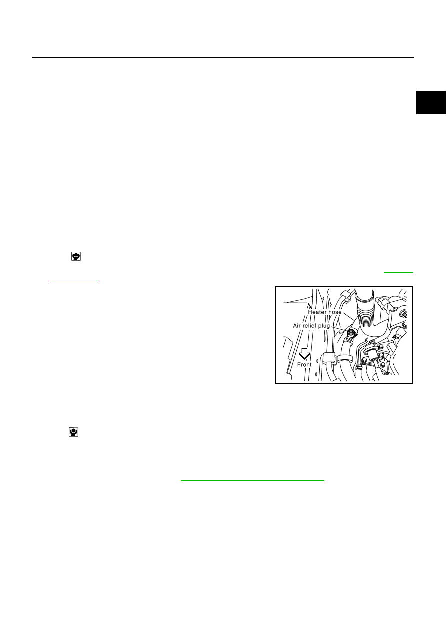
Remove air relief plug on heater hose.

3.

Fill radiator with water until water spills from the air relief hole, then close air relief plug. Fill radiator and
reservoir tank with water and reinstall radiator cap.

4.

Run the engine and warm it up to normal operating temperature.

5.

Rev the engine two or three times under no-load.

6.

Stop the engine and wait until it cools down.

7.

Drain water from the system. Refer to 

CO-11, "DRAINING ENGINE COOLANT"

 .

8.

Repeat steps 1 through 7 until clear water begins to drain from radiator.

Radiator drain plug:             

 : 1.2 N·m (0.12 kg-m, 11 in-lb)

SBIA0445E

Air relief plug:

 : 1.2 N·m (0.12 kg-m, 11 in-lb)

CO-14

[VQ35DE]

RADIATOR

RADIATOR

PFP:21400

Components

NBS004QS

Refer to 

GI-11, "Components"

  for symbols in the figure.

Removal and Installation

NBS004QT

WARNING:

Do not remove radiator cap when engine is hot. Serious burns could occur from high-pressure engine
coolant escaping from radiator. Wrap a thick cloth around the cap. Slowly turn it a quarter of a turn to
release built-up pressure. Carefully remove radiator cap by turning it all the way.

REMOVAL

1.

Remove the following parts:

Front engine undercover (power tool). 

Engine room cover (RH and LH). Refer to 

EM-15, "ENGINE ROOM COVER"

 .

Air duct (inlet) and air cleaner case assembly. Refer to 

EM-19, "AIR CLEANER AND AIR DUCT"

 .

1.

Reservoir tank cap

2.

Reservoir tank

3.

Reservoir tank bracket

4.

Reservoir tank hose

5.

Radiator hose (upper)

6.

Air guide

7.

Mount bracket (RH)

8.

Mounting rubber (upper)

9.

A/C condenser

10. Radiator cap

11.

Mount bracket (LH)

12. Radiator

13. Mounting rubber (lower)

14. A/T fluid cooler hose

15. A/T fluid cooler hose

16. O-ring

17. Drain plug

18. Radiator hose (lower)

19. Cooling fan assembly

A.

To water outlet

B.

To water inlet

C.

To transmission

D.

To transmission

PBIC4717E

RADIATOR

CO-15

[VQ35DE]

C

D

E

F

G

H

I

J

K

L

M

A

CO

2.

Remove front grille and front grille support. Refer to 

EI-16, "FRONT GRILLE"

 . 

NOTE:
If stopping at the removal and installation of the cooling fan assembly, this procedure is not necessary.

3.

Drain engine coolant from radiator. Refer to 

CO-11, "Changing Engine Coolant"

 .

CAUTION:

Perform this step when the engine is cold.

Do not spill engine coolant on drive belts.

4.

Remove the A/C piping bracket from left side member, and then move the A/C piping out of the way.

5.

Disconnect A/T fluid cooler hoses from radiator.

Install blind plug to avoid leakage of A/T fluid.

6.

Remove radiator hoses (upper and lower) and reservoir tank hose.

CAUTION:

Be careful not to allow engine coolant to contact drive belts.

7.

Remove cooling fan assembly (1). Refer to 

CO-22, "COOLING

FAN"

 .

CAUTION:

Do not damage or scratch radiator core when removing.

8.

Remove radiator as follows:

a.

Remove mount bracket (RH and LH).

b.

Pull the radiator (1) rearward from the vehicle, and then remove
the mounting bolts (3) and A/C condenser (2).

NOTE:
Figure shows right side.

c.

Lift up and pull the radiator (4) rearward, and then remove the mounting rubber (lower) (3) from the radia-
tor core support (2).

CAUTION:

At this time, A/C condenser is on the lower end of radiator
front surface. Minimize the movement to the rear side.

d.

Lift up the A/C condenser to disengage the lower end of front surface, and then remove the radiator.

CAUTION:

Be careful not to damage radiator and A/C condenser core.

KBIA3587J

KBIA3586J

1

: A/C condenser

: Engine front

PBIC3389E

CO-16

[VQ35DE]

RADIATOR

Minimize the lift of A/C condenser to prevent load from being applied to A/C piping.

e.

After removing the radiator, place the A/C condenser on the radiator core support to prevent load from
being applied to piping. And then, temporarily secure them using a rope to prevent them from being
dropped.

INSTALLATION

Installation is the reverse order of removal.

INSPECTION AFTER INSTALLATION

Check for leaks of engine coolant using the radiator cap tester adapter (commercial service tool) and the
radiator cap tester (commercial service tool). Refer to 

CO-11, "LEAK CHECK"

 .

Start and warm up the engine. Visually make sure that there is no leaks of engine coolant and A/T fluid.

Checking Radiator Cap

NBS004QU

Check valve seat of radiator cap. 

Check if valve seat is swollen to the extent that the edge of the
plunger cannot be seen when watching it vertically from the top.

Check if valve seat has no soil and damage.

Pull negative-pressure valve to open it, and make sure that it
close completely when released.

Make sure that there is no dirt or damage on the valve seat of
radiator cap negative-pressure valve. 

Make sure that there are no unusualness in the opening and
closing conditions of negative-pressure valve.

Check radiator cap relief pressure.

When connecting radiator cap to the radiator cap tester (com-
mercial service tool) (A) and the radiator cap tester adapter
(commercial service tool) (B), apply engine coolant to the cap
seal surface. 

Replace radiator cap if there is an unusualness related to the above three.

CAUTION:

When installing radiator cap, thoroughly wipe out the radiator filler neck to remove any waxy residue
or foreign material.

Checking Radiator

NBS004QV

Check radiator for mud or clogging. If necessary, clean radiator as follows.

PBIC2816E

SMA967B

Standard:

78 - 98 kPa (0.8 - 1.0 kg/cm

2

 , 11 - 14 psi)

Limit:

59 kPa (0.6 kg/cm

2

 , 9 psi) 

PBIC5122J


Content   ..  341  342  343  344   ..