Infiniti M35/M45 Y50. Manual - part 339
ACTUATOR AND ELECTRIC UNIT (ASSEMBLY)
BRC-57
[VDC/TCS/ABS]
C
D
E
G
H
I
J
K
L
M
A
B
BRC
ACTUATOR AND ELECTRIC UNIT (ASSEMBLY)
PFP:47660
Removal and Installation
NFS000RC
COMPONENT
CAUTION:
Be careful of the following.
●
Before servicing, disconnect the battery cable from negative terminal.
●
To remove brake tube, use a flare nut wrench to prevent flare nuts and brake tube from being dam-
aged. To install, use flare nut torque wrench.
●
Do not apply excessive impact to ABS actuator and electric unit (control unit), such as dropping it.
●
Do not remove and install actuator by holding harness.
●
After work is completed, bleed air from brake tube. Refer to
BR-10, "Bleeding Brake System"
●
After installing harness connector in the ABS actuator and electric unit (control unit), make sure
connector is securely locked.
REMOVAL
1.
Remove cowl top cover. Refer to
2.
Disconnect ABS actuator and electric unit (control unit) connector.
3.
Loosen brake tube flare nuts, then remove brake tubes from ABS actuator and electric unit (control unit).
4.
Remove tire.
5.
Remove fender protector (rear): (front LH side). Refer to
6.
Remove ABS actuator and electric unit (control unit) bracket mounting nut.
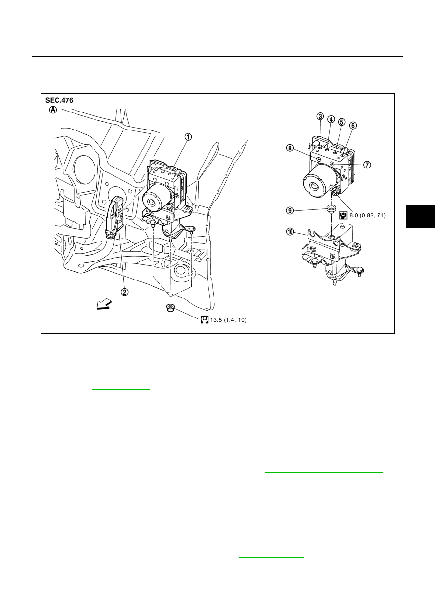
1.
ABS actuator and electric unit (con-
trol unit)
2.
Connector
3.
To front RH brake caliper
4.
To rear LH brake caliper
5.
To rear RH brake caliper
6.
To front LH brake caliper
7.
From master cylinder primary side
8.
From master cylinder secondary side 9.
Bushing
10.
Bracket
A.
Left side of dash panel
Refer to GI section
for symbol marks in the figure.
SFIA3018E