Infiniti M35/M45 Y50. Manual - part 324


  Index      Infiniti     Infiniti M35/M45 Y50 - service repair manual 2007 year


Search            copyright infringement  


Content   ..  322  323  324  325   ..


Infiniti M35/M45 Y50. Manual - part 324


REAR DISC BRAKE

BR-31

C

D

E

G

H

I

J

K

L

M

A

B

BR

Disassembly and Assembly of Brake Caliper Assembly

NFS000SL

NOTE:
Do not remove torque member, pads, shims, shim cover, and pad retainers when disassembling and assem-
bling cylinder body assembly.

DISASSEMBLY

1.

Remove sliding pin bolt, and then remove cylinder body from torque member.

CAUTION:

Do not drop pads, shims, shim cover and pad retainers from torque member.

2.

Remove sliding pin boots from torque member.
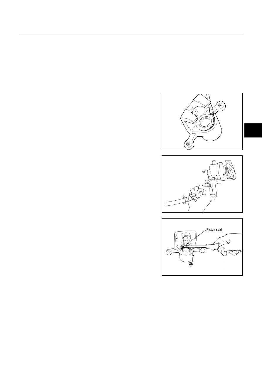
3.

Remove retaining ring from cylinder body using a flat-bladed
screwdriver as shown in the figure.

4.

Place a wooden block as shown in the figure, and blow air from
union bolt mounting hole to remove piston and piston boot.

CAUTION:

Do not get fingers caught in the piston.

5.

Remove piston seal from cylinder body using a flat-bladed
screwdriver.

CAUTION:

Be careful not to damage a cylinder inner wall.

INSPECTION AFTER DISASSEMBLY
Cylinder Body

Check the inner wall of cylinder for corrosion, wear, and damage. If a malfunction is detected, replace cylinder
body.

CAUTION:

Clean cylinder body using new brake fluid. Never use mineral oils such as gasoline or kerosene.

Torque Member

Check torque member for wear, cracks, and damage. Replace if there are.

Piston

Check the piston surface for corrosion, wear, and damage. If a malfunction is detected, replace applicable
part.

SBR028A

BRD0041D

SFIA2277E

BR-32

REAR DISC BRAKE

CAUTION:

A piston sliding surface is plated. Do not polish with sandpaper.

Sliding Pin Bolt, Sliding Pin Boot

Check sliding pin bolt and sliding pin boot for wear, damage, and cracks. Replace if there are.

ASSEMBLY

1.

Apply polyglycol ether based lubricant to piston seal, and install
them to cylinder body.

CAUTION:

Do not reuse piston seal.

2.

Apply rubber grease to piston boot. Cover the piston end with
the piston boot, and then install cylinder side lip on the piston
boot securely into the groove on cylinder body.

CAUTION:

Do not reuse piston boot.

3.

Apply brake fluid to piston. Push piston into cylinder body by
hand and push piston boot piston side lip into the piston groove.

CAUTION:

Press the piston evenly and vary the pressing point to pre-
vent cylinder inner wall from being rubbed.

4.

Secure piston boot with retaining ring.

CAUTION:

Make sure that boot is securely engaged in the groove on
cylinder body.

Do not reuse retainer ring.

5.

Install sliding pin boot to torque member.

6.

Install the cylinder body to torque member, and then tighten slid-
ing pin bolt to the specified torque. Refer to 

BR-28, "Compo-

nents"

 .

SFIA2278E

SFIA2498E

SFIA2279E

SFIA2280E

REAR DISC BRAKE

BR-33

C

D

E

G

H

I

J

K

L

M

A

B

BR

DISC ROTOR INSPECTION
Visual Inspection

Check surface of disc rotor for uneven wear, cracks, and serious damage. Replace if there are.

Runout Inspection

1.

Fix disc rotor to wheel hub using wheel nuts (2 or more posi-
tions). 

2.

Inspect runout using dial gauge. [Measured at 10 mm (0.39 in)
inside disc edge.]

NOTE:
Before measuring, make sure that wheel bearing axial end play
is within the specification. Refer to 

RAX-5, "WHEEL BEARING

INSPECTION"

 .

3.

When runout exceeds limit value, displace mounting positions of
disc rotor by one hole. And then find a position of the minimum value for runout. 

4.

Replace disc rotor if it is outside repair limit after performing the above operation.

Thickness Inspection

Check the thickness of the disc rotor using a micrometer. Replace
disc rotor if the thickness is under the wear limit.

BRAKE BURNISHING PROCEDURE

Burnish contact surfaces between disc rotors and pads according to following procedure after refinishing or
replacing rotors, after replacing pads, or if a soft pedal occurs at very low mileage.

CAUTION:

Be careful of vehicle speed because the brake does not operate easily until pad and disc rotor are
securely fitted.

Only perform this procedure under safe road and traffic conditions. Use extreme caution.

1.

Drive the vehicle on a straight, flat road.

2.

Depress brake pedal with the power to stop vehicle within 3 to 5 seconds until the vehicle stops.

3.

Drive without depressing brake for a few minutes to cool the brake.

4.

Repeat steps 1 to 3 until pad and disc rotor are securely fitted.

Runout limit 

: 0.055 mm (0.0022 in)

(With it attached to the vehicle)

BRA0697D

Standard thickness

: 16.0 mm (0.631 in)

Wear limit

: 14.0 mm (0.551 in)

Thickness variation
(Measured at 8 positions)

: 0.015 mm (0.0006in)

SFIA2284E

BR-34

SERVICE DATA AND SPECIFICATIONS (SDS)

SERVICE DATA AND SPECIFICATIONS (SDS)

PFP:00030

General Specifications

NFS000SM

Unit: mm (in)

Brake Pedal

NFS000SN

Unit: mm (in)

Brake Booster

NFS000SO

Vacuum type

Unit: mm (in)

Check Valve

NFS000SP

Front Disc Brake

NFS000SQ

Unit: mm (in)

Rear Disc Brake

NFS000SR

Unit: mm (in)

Front brake

Cylinder bore diameter

45.0 (1.772) 

×

 2 

Pad length 

×

 width 

×

 thickness

132.0 

×

 50.0 

×

 11.0 (5.20 

×

 1.969 

×

 0.433)

Rotor outer diameter 

×

 thickness

320 

×

 28 (12.60 

×

 1.10)

Rear brake 

Cylinder bore diameter

42.86 (1.687)

Pad length 

×

 width 

×

 thickness

83.0 

×

 31.9 

×

 8.5 (3.268 

×

 1.256 

×

 0.335)

Rotor outer diameter 

×

 thickness

308 

×

 16 (12.13 

×

 0.63)

Master cylinder

Cylinder bore diameter

25.4 (1)

Control valve

Valve model

Electric brake force distribution

Brake booster

Diaphragm diameter

 255 (10)

Recommended brake fluid

DOT 3

Brake pedal height (from dash lower panel top surface) 

157 

 167 (6.18 

 6.57) 

Depressed pedal height
[under a force of 490 N (50 kg, 110 lb) with engine running]

90 (3.54) or more 

Clearance between threaded end of the stop lamp switch/brake 
switch and bracket 

0.74 

 1.96 (0.0291 

0.0772)

Pedal play

 11 (0.12 

 0.43)

Input rod installation standard dimension

125 (4.92)

Vacuum leakage 
[at vacuum of – 66.7 kPa (– 500 mmHg, – 19.69 inHg)]

Within 1.3 kPa (10 mmHg, 0.39 inHg) of vacuum for 15 seconds

Brake pad

Standard thickness 

11.0 (0.433)

Repair limit thickness

2.0 (0.079)

Disc rotor

Standard thickness 

28.0 (1.102)

Wear limit

26.0 (1.024)

Thickness variation (measured at 8 positions)

0.015 (0.0006)

Runout limit (with it attached to the vehicle)

0.035 (0.0014) 

Brake pad

Standard thickness 

8.5 (0.335)

Repair limit thickness

2.0 (0.079)

Disc rotor

Standard thickness 

16.0  (0.631)

Wear limit

14.0 (0.551)

Thickness variation (measured at 8 positions)

0.015 (0.0006)

Runout limit (with it attached to the vehicle)

0.055 (0.0022) 


Content   ..  322  323  324  325   ..