Infiniti M35/M45 Y50. Manual - part 319
BRAKE TUBE AND HOSE
BR-11
C
D
E
G
H
I
J
K
L
M
A
B
BR
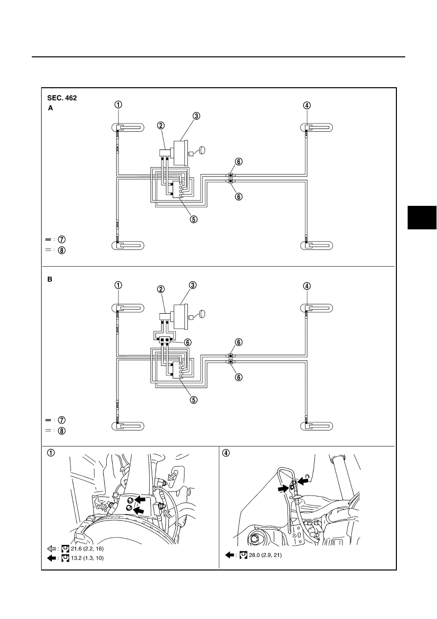
BRAKE TUBE AND HOSE
PFP:46300
Hydraulic Circuit
NFS000RZ
SFIA3096E
|
|
|
BRAKE TUBE AND HOSE BR-11 C D E G H I J K L M A B BR BRAKE TUBE AND HOSE PFP:46300 Hydraulic Circuit NFS000RZ SFIA3096E |