Infiniti M35/M45 Y50. Manual - part 299


  Index      Infiniti     Infiniti M35/M45 Y50 - service repair manual 2007 year


Search            copyright infringement  


Content   ..  297  298  299  300   ..


Infiniti M35/M45 Y50. Manual - part 299


IVIS (INFINITI VEHICLE IMMOBILIZER SYSTEM-NATS)

BL-265

C

D

E

F

G

H

J

K

L

M

A

B

BL

CONSULT-II

NIS0020N

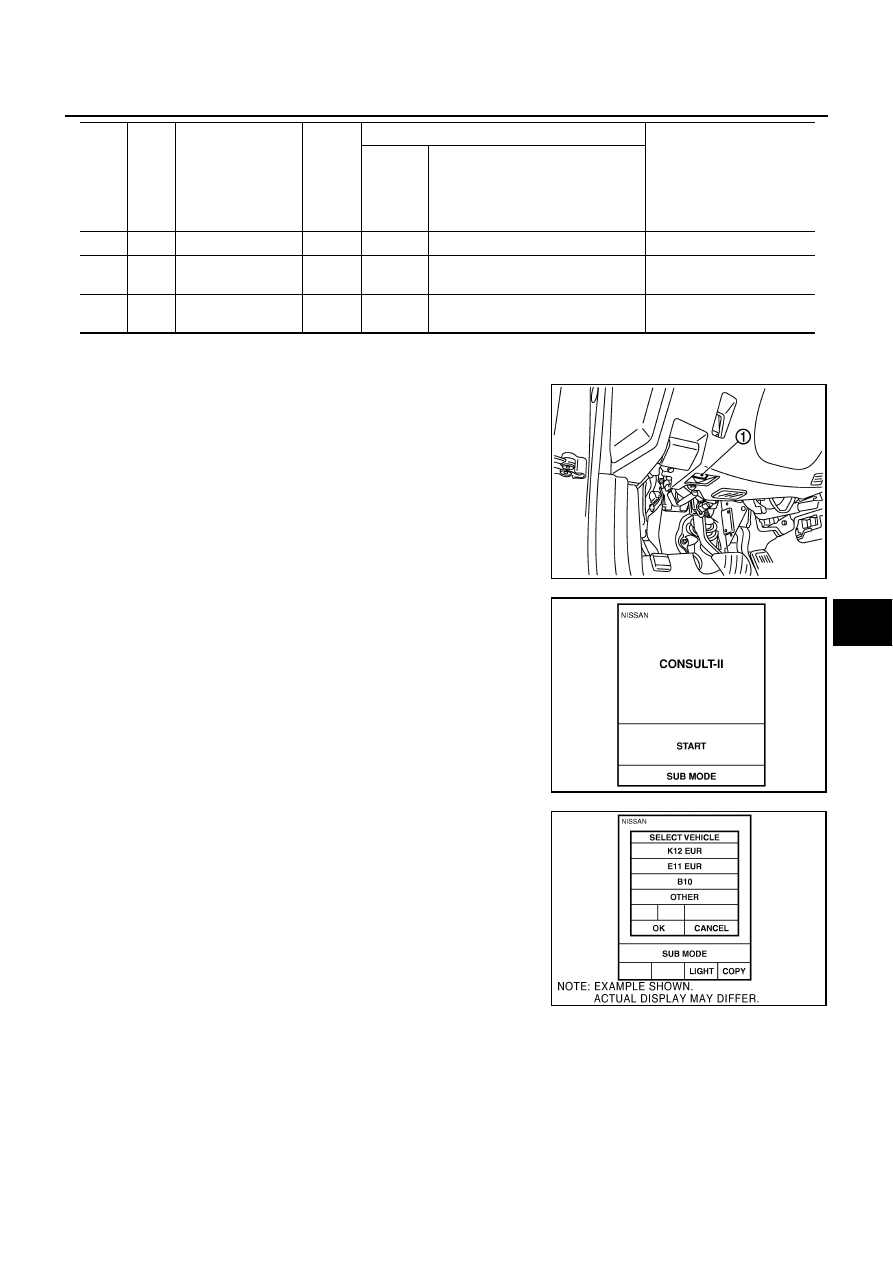
CONSULT-II INSPECTION PROCEDURE

1.

Turn ignition switch OFF.

2.

Insert IVIS (NATS) program card into CONSULT-II.

3.

Connect CONSULT-II and CONSULT-II CONVERTER to data
link connector (1).

4.

Turn ignition switch ON.

5.

Touch “START”.

6.

Touch “OTHER”.

14

SB

Power source (fuse)

Input

Battery voltage

15

L

Power source (fus-
ible link)

Input

Battery voltage

17

G

Power source (fus-
ible link)

Input

Battery voltage

Ter-

minal 

No.

Wire 

color

Item

Signal 

Input/

Output

Condition

Voltage (V)

(Approx.)

Push-

button 

ignition 

switch 

position

Operation or conditions

Program card

: NATS (AEN06B)

PBIB2712E

PBR455D

PIIB8627E

BL-266

IVIS (INFINITI VEHICLE IMMOBILIZER SYSTEM-NATS)

7.

Select “NATS V.5.0”.
If “NATS V5.0” is not indicated, go to 

GI-39, "CONSULT-II Data

Link Connector (DLC) Circuit"

 .

8.

Perform each diagnostic test mode according to each service
procedure.

For further information, see the CONSULT-II Operation Manual
NATS-IVIS/NVIS.

CONSULT-II DIAGNOSTIC TEST MODE FUNCTION

NOTE:

When any initialization is performed, all ID previously registered will be erased and all NATS ignition keys
must be registered again.

The engine cannot be started with an unregistered key. In this case, the system will show “DIFFERENCE
OF KEY” or “LOCK MODE” as a self-diagnostic result on the CONSULT-II screen.

PIIB6275E

PIIB6276E

System

Diagnosis mode

Description

Reference 

page

NATS V5.0

C/U INTIALIZATION

Perform registration again after repair, part replacement, and 
additional key ID registration.

CAUTION:

“Control Unit Initialization” is activated only after per-
forming “Release steering lock”.

Refer to the 
Technical Bul-
letin.

SELF-DIAG RESULTS

Malfunctioning system stored in the ECM is displayed.

Printing the contents

Erasing the error record

BL-268

NATS BCM or S/ENT

PIN READ

The specified numbers of each control unit for acquisition of 
password for control unit initialization are displayed

Refer to the 
Technical Bul-
letin.

STEERING LOCK 
RELEASE

If the engine switch cannot be operated (the steering lock 
cannot be released), release the steering lock forcibly and 
make the engine switch operation possible.

CAUTION:

Always perform “Control Unit Initialization” and “Immo-
bilizer ID Registration” after performing “Release Steer-
ing Lock”.

Refer to the 
Technical Bul-
letin.

SELF-DIAG RESULTS

Malfunctioning system stored in the BCM is displayed.

Printing the contents

Erasing the error record

BL-268

NATS I-KEY

SELF-DIAG RESULTS

Malfunctioning system stored in the Intelligent Key unit is 
displayed.

Printing the contents

Erasing the error record

BL-269

IVIS (INFINITI VEHICLE IMMOBILIZER SYSTEM-NATS)

BL-267

C

D

E

F

G

H

J

K

L

M

A

B

BL

In rare case, “CHAIN OF ECM-IMMU” might be stored as a self-diagnostic result during key registration
procedure, even if the system is not malfunctioning.

HOW TO READ SELF-DIAGNOSTIC RESULTS

PIIB6280E

BL-268

IVIS (INFINITI VEHICLE IMMOBILIZER SYSTEM-NATS)

“NATS V5.0” SELF-DIAGNOSTIC RESULTS ITEM CHART

“NATS BCM OR S/ENT” SELF-DIAGNOSTIC RESULTS ITEM CHART

Suspect Systems

Description

Possible malfunction

Action to take/Reference page

NO DTC

NO DTC

DON'T ERASE BEFORE 
CHECKING ENG DIAG

There is the engine trouble 
diagnosis information in ECM
(ECM trouble diagnosis is nec-
essary separately)

Engine control system malfunc-
tion

There is the engine trouble 
diagnosis information in ECM. 
Check the trouble diagnostic 
results of “ENGINE” before 
that.

LOCK MODE
[P1610]

The immobilizer switches to the 
mode that prevents the engine 
from being started. If the ID ver-
ification between BCM and 
ECM is NG, the ID verification 
malfunction between remote 
control starter and BCM may be 
detected 5 times or more.

When “LOCK MODE” is dis-
played, check for any other dis-
played malfunction, and then 
erase the self-diagnostic results 
after replacement.

ID DISCORD, IMM-ECM
[P1611]

The ID verification results 
between BCM and ECM are 
NG. The registration is neces-
sary.

Registration of ECM is not com-
pleted

BL-277

ECM malfunction

Replace ECM.

CHAIN OF ECM-IMMU
[P1612]

Inactive communication 
between ECM and BCM

Open circuit in battery power 
supply line of BCM

BL-275

Open circuit in ignition power 
supply line of BCM

Open circuit in ground of BCM

Short circuit in communication 
line between BCM and ECM to 
power supply line

Open circuit in communication 
line between BCM and ECM

Short circuit in communication 
line between BCM and ECM to 
ground

ECM malfunction

BCM malfunction

CHAIN OF IMMU-KEY
[P1614]

BCM malfunction

BCM malfunction

BCS-15

Suspect Systems

Description

Possible malfunction

Action to take/Reference page

NO DTC

NO DTC

ID DISCORD BCM-ECM
[B2192]

The ID verification results 
between BCM and ECM are 
NG. The registration is neces-
sary.

Registration of ECM is not com-
pleted

Perform “Control Unit Initializa-
tion”, and then perform the ID 
registration. Refer to the Tech-
nical Bulletin.

ECM malfunction

Replace ECM.

CHAIN OF BCM-ECM
[B2193]

Inactive communication 
between ECM and BCM

Short circuit in communication 
line between BCM and ECM to 
power supply line

Malfunction have occurred in 
CAN communication
Check “Self-diagnostic Results” 
of “Intelligent Key” using CON-
SULT-II. Refer to 

BL-150, 

"SELF-DIAGNOSTIC 
RESULTS"

 .

Open circuit in communication 
line between BCM and ECM

Short circuit in communication 
line between BCM and ECM to 
ground

ECM malfunction

Replace ECM.


Content   ..  297  298  299  300   ..