Infiniti M35/M45 Y50. Manual - part 290
VEHICLE SECURITY (THEFT WARNING) SYSTEM
BL-229
C
D
E
F
G
H
J
K
L
M
A
B
BL
Terminals and Reference Value of BCM
NIS001ZZ
Terminals and Reference Value of IPDM E/R
NIS00200
Termi-
nal
Wire
color
Item
Signal
Input/
Output
Condition
Voltage [V]
(Approx.)
11
V
Power supply (ACC)
Input
Ignition switch (ACC or ON
position)
Battery voltage
12
P
Front door switch
passenger side signal
Input
ON (Open)
→
OFF
(Closed)
0
→
Battery voltage
13
O/L
Rear door switch RH signal
Input
ON (Open)
→
OFF
(Closed)
0
→
Battery voltage
22
G
Power window serial link
Input/
Output
Ignition switch ON or power
window timer operating
23
W/V
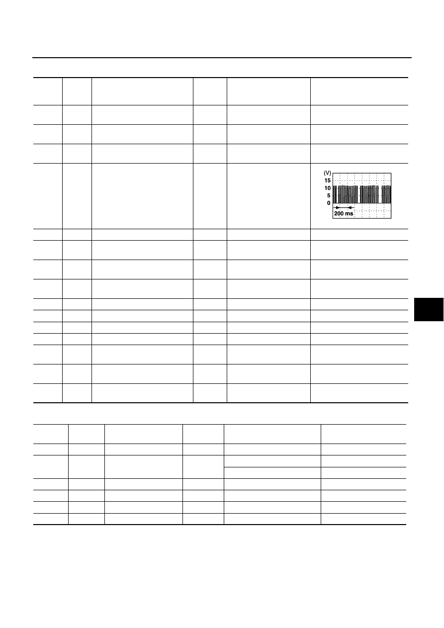
Security indicator lamp
Output
Goes off
→
Illuminates
Battery voltage
→
0
37
LG
Key switch signal
Input
Key inserted in key slot
→
key removed from key slot
Battery voltage
→
0
39
L
CAN-H
Input/
Output
—
—
40
P
CAN-L
Input/
Output
—
—
42
P
Power source (fuse)
Input
—
Battery voltage
52
B
Ground
—
—
0
55
W
Battery power supply (fusible link)
Input
—
Battery voltage
56
W
Trunk lid key cylinder switch
Input
Neutral
→
Unlock
Battery voltage
→
0
57
SB
Trunk room lamp switch signal
Input
ON (Open)
→
OFF
(Closed)
0
→
Battery voltage
62
V
Front door switch
driver side signal
Input
ON (Open)
→
OFF
(Closed)
0
→
Battery voltage
63
R/G
Rear door switch LH signal
Input
ON (Open)
→
OFF
(Closed)
0
→
Battery voltage
PIIA2344J
Terminal Wire
color
Item
Signal
Input/Output
Condition
Voltage [V]
(Approx.)
38
B
Ground (power)
—
—
0
48
G/B
Horn relay control signal
Output
Panic alarm is operating
0
Other than above
Battery voltage
49
L
CAN-H
Input/Output
—
—
50
P
CAN-L
Input/Output
—
—
51
B
Ground (signal)
—
—
0
60
LG/B
Hood switch signal
Input
ON (Open)
→
OFF (closed)
0
→
Battery voltage