Infiniti M35/M45 Y50. Manual - part 287
VEHICLE SECURITY (THEFT WARNING) SYSTEM
BL-217
C
D
E
F
G
H
J
K
L
M
A
B
BL
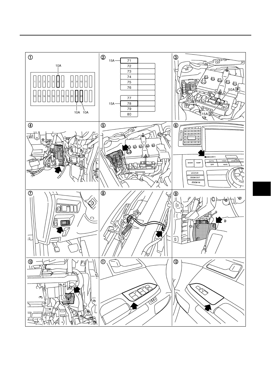
VEHICLE SECURITY (THEFT WARNING) SYSTEM
PFP:28491
Component Parts and Harness Connector Location
NIS001ZT
PIIB5863E
|
|
|
VEHICLE SECURITY (THEFT WARNING) SYSTEM BL-217 C D E F G H J K L M A B BL VEHICLE SECURITY (THEFT WARNING) SYSTEM PFP:28491 Component Parts and Harness Connector Location NIS001ZT PIIB5863E |