Infiniti M35/M45 Y50. Manual - part 275
INTELLIGENT KEY SYSTEM/ENGINE START FUNCTION
BL-169
C
D
E
F
G
H
J
K
L
M
A
B
BL
2.
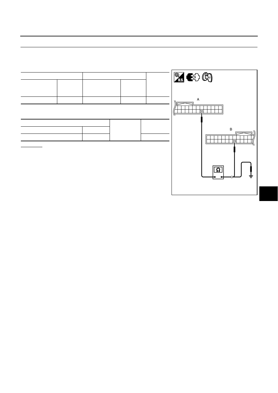
CHECK HARNESS CONTINUITY
1.
Turn ignition switch OFF.
2.
Disconnect Intelligent Key unit and unified meter and A/C amp. Connector.
3.
Check continuity between Intelligent Key unit connector and unified meter and A/C amp. Connector.
4.
Check continuity between Intelligent Key unit connector and
ground.
OK or NG
OK
>>
●
If the measured value is not waveform but 0V con-
stant, the harness or connector between the using
receiving the vehicle speed signal from unified meter
and A/C amp. may be malfunctioning. Check these
wirings.
●
If the measured value is not waveform but 5V or 12V
constant, replace unified meter and A/C amp.
NG
>> Repair or replace harness.
A
B
Continuity
Intelligent Key
unit connector
Terminal
Unified meter and
A/C amp.
connector
Terminal
M32
35
M64
28
Yes
A
Ground
Continuity
Intelligent Key unit connector
Terminal
M32
35
No
PIIB6243E