Infiniti M35/M45 Y50. Manual - part 256


  Index      Infiniti     Infiniti M35/M45 Y50 - service repair manual 2007 year


Search            copyright infringement  


Content   ..  254  255  256  257   ..


Infiniti M35/M45 Y50. Manual - part 256


INTELLIGENT KEY SYSTEM

BL-93

C

D

E

F

G

H

J

K

L

M

A

B

BL

4. 

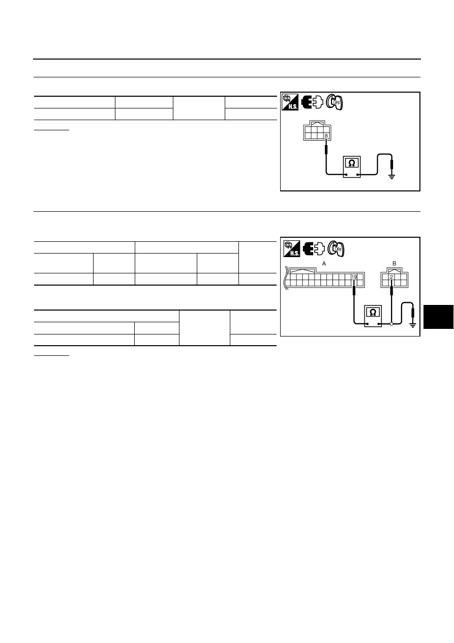
CHECK KEY SLOT GROUND CIRCUIT

Check continuity between key slot connector and ground.

OK or NG

OK

>> GO TO 5.

NG

>> Repair or replace key slot ground circuit.

5. 

CHECK KEY SWITCH CIRCUIT

1.

Disconnect Intelligent Key unit connector.

2.

Check continuity between Intelligent Key unit connector 7 and key slot connector.

3.

Check continuity between Intelligent Key unit connector and
ground.

OK or NG

OK

>> Check the condition of harness and harness connector.

NG

>> Repair or replace harness between Intelligent Key unit and key slot.

Key slot connector

Terminal

Ground

Continuity

M14

8

Yes

PIIB6322E

A

B

Continuity 

Intelligent Key 
unit connector

Terminal

Key slot connector

Terminal

M32

19

M14

2

Yes

A

Ground

Continuity 

Intelligent Key unit connector

Terminal

M32

19

No

PIIB6323E

BL-94

INTELLIGENT KEY SYSTEM

Check Door Switch

NIS001XO

1. 

CHECK DOOR SWITCH INPUT SIGNAL

 With CONSULT-II

Check door switches (“DOOR SW-DR”, “DOOR SW-AS”, “DOOR SW-RL” and “DOOR SW-RR”) in “DATA
MONITOR” mode with CONSULT-II.

 Without CONSULT-II

1.

Turn ignition switch OFF.

2.

Check voltage between BCM connector and ground.

OK or NG

OK

>> Door switch circuit is OK.

NG

>> GO TO 2.

Monitor item

Condition

DOOR SW-DR

CLOSE 

 OPEN: OFF 

 ON

DOOR SW-AS

DOOR SW-RL

DOOR SW-RR

PIIA6469E

Terminals

Door condition

Voltage (V)

(Approx.)

(+)

(–)

BCM

connector

Terminal

M1

12

Ground

Front 

passenger 

side

OPEN

0

CLOSE

Battery voltage

13

Rear RH 

side

OPEN

0

CLOSE

Battery voltage

M3

62

Driver side

OPEN

0

CLOSE

Battery voltage

63

Rear LH 

side

OPEN

0

CLOSE

Battery voltage

PIIB6324E

INTELLIGENT KEY SYSTEM

BL-95

C

D

E

F

G

H

J

K

L

M

A

B

BL

2. 

CHECK DOOR SWITCH

1.

Turn ignition switch OFF.

2.

Disconnect door switch connector.

3.

Check door switch.

OK or NG

OK

>> GO TO 3.

NG

>> Replace malfunction door switch.

3. 

CHECK DOOR SWITCH CIRCUIT 

1.

Disconnect BCM connector.

2.

Check continuity between BCM connector and door switch connector.

3.

Check continuity between BCM connector and ground.

OK or NG

OK

>> GO TO 4.

NG

>> Repair or replace harness between BCM and door

switch.

Terminal

Door switch

Continuity

Door switch

2

Ground part of 

door switch

Pushed

No

Released

Yes

PIIB5977E

A

B

Continuity 

BCM connector

Terminal

Door switch

connector

Terminal

M1

12

B35

2

Yes

13

B403

M3

62

B11

63

B53

A

Ground

Continuity 

BCM connector

Terminal

M1

12

No

13

M3

62

63

PIIB6325E

BL-96

INTELLIGENT KEY SYSTEM

4. 

CHECK BCM OUTPUT SIGNAL

1.

Connect BCM connector.

2.

Check voltage between BCM connector and ground.

OK or NG

OK

>> Check the condition of harness and connector.

NG

>> Replace BCM.

Terminals

Voltage (V)

(Approx.)

(+)

(–)

BCM connector

Terminal

M1

12

Ground

Battery voltage

13

M3

62

63

PIIB6324E


Content   ..  254  255  256  257   ..