Infiniti M35/M45 Y50. Manual - part 220
TROUBLE DIAGNOSIS
AV-257
[WITH MOBILE ENTERTAINMENT SYSTEM]
C
D
E
F
G
H
I
J
L
M
A
B
AV
8.
CHECK REAR VIEW IMAGE SIGNAL
Check signal between front display unit harness connector M203 ter-
minal 11 and ground.
OK or NG
OK
>> Replace front display unit.
NG
>> Replace camera control unit.
DVD IMAGE IS NOT DISPLAYED
1.
CHECK HARNESS BETWEEN AV (NAVI) CONTROL UNIT AND VIDEO DISTRIBUTOR
1.
Disconnect AV (NAVI) control unit connector and video distributor connector.
2.
Check continuity between AV (NAVI) control unit harness con-
nector (A) M210 terminal 50 and video distributor harness con-
nector (B) M207 terminal 48.
OK or NG
OK
>> GO TO 2.
NG
>> Repair harness or connector.
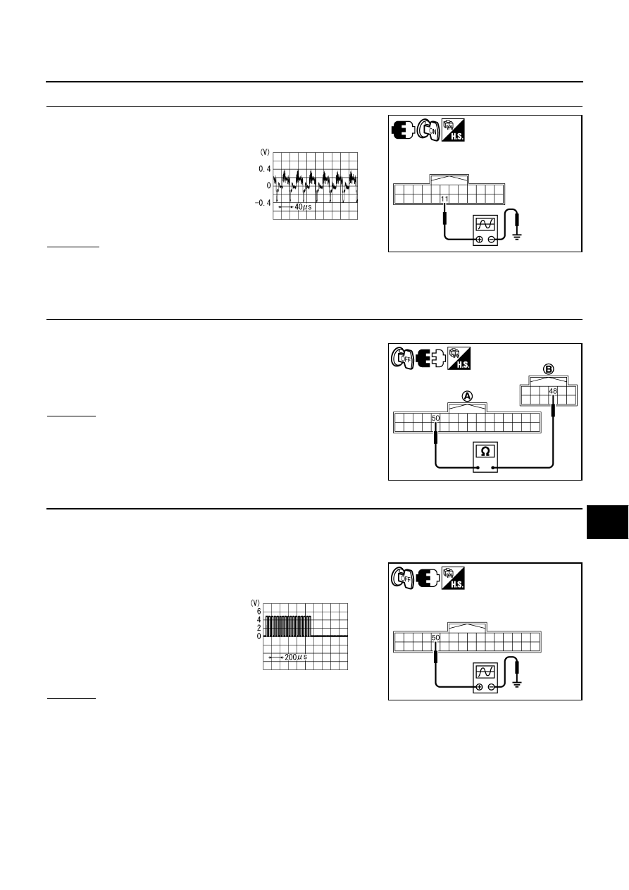
2.
CHECK RGB AREA SIGNAL FOR AV (NAVI) CONTROL UNIT
1.
Connect AV (NAVI) control unit connector and video distributor connector.
2.
Turn ignition switch ON.
3.
Shift the selector lever in R position.
4.
Check signal between AV (NAVI) control unit harness connector
M210 terminal 50 and ground.
OK or NG
OK
>> GO TO 3.
NG
>> Replace AV (NAVI) control unit.
11 – Ground:
SKIB4612E
SKIB2251J
50 – 48
: Continuity should exist.
SKIB4613E
50 – Ground:
SKIB4614E
PKIB4948J