Infiniti M35/M45 Y50. Manual - part 211
TERMINALS AND REFERENCE VALUE FOR CONTROL UNIT
AV-221
[WITH MOBILE ENTERTAINMENT SYSTEM]
C
D
E
F
G
H
I
J
L
M
A
B
AV
*: BOSE surround 5.1ch system
33
*
(R/Y)
–
Shield
–
–
–
–
34
*
(R/L)
42
*
(G)
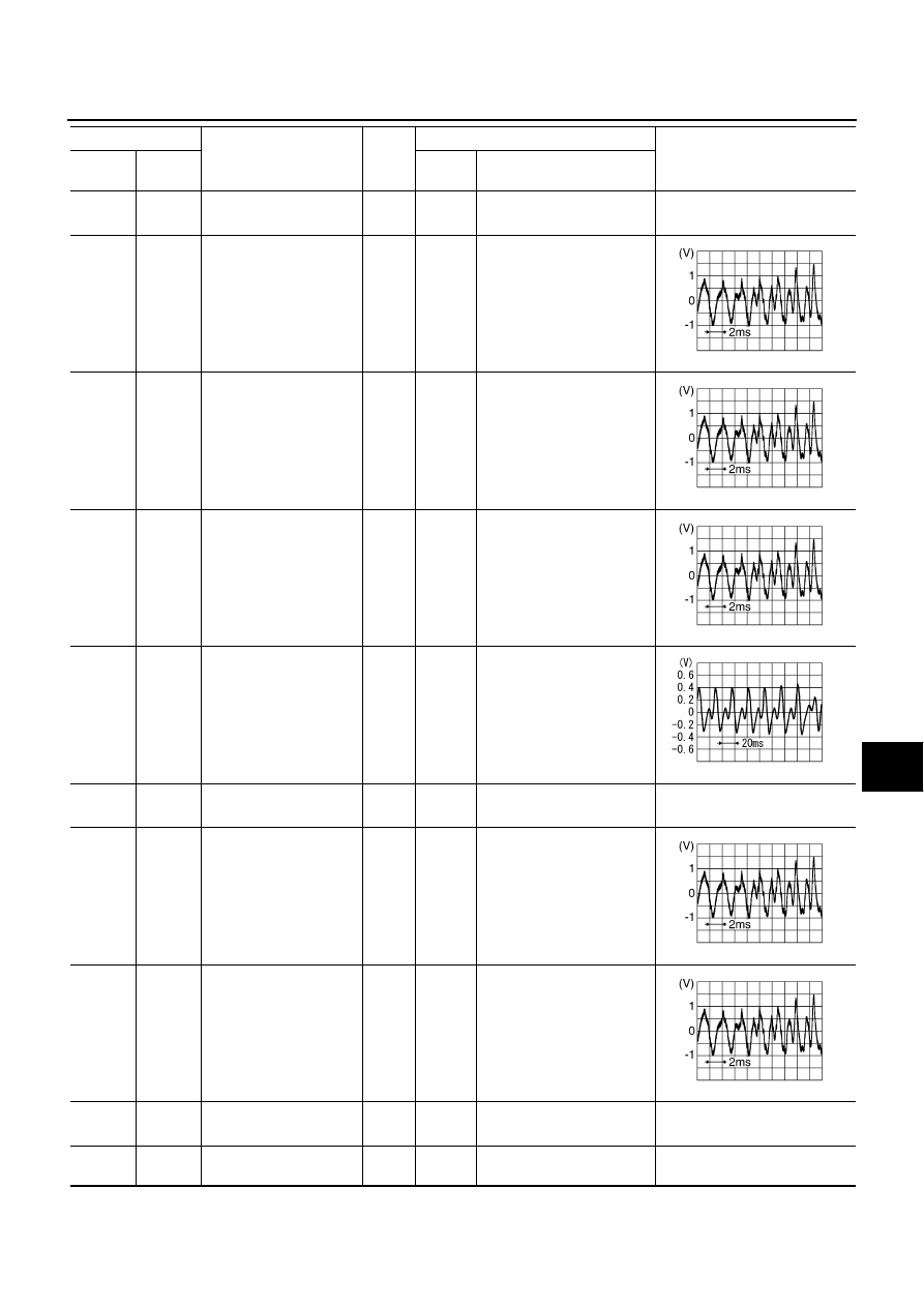
DVD sound signal front
RH
Output
ON
When playing DVD
CAUTION
35
*
(L/Y)
43
*
(L)
DVD sound signal front
LH
Output
ON
When playing DVD
CAUTION
36
*
(R/B)
44
*
(R)
DVD sound signal
center
Output
ON
When playing DVD
CAUTION
37
*
(Y/B)
45
*
(Y)
DVD sound signal woofer
Output
ON
When playing DVD
CAUTION
38
*
(G/R)
–
Shield
–
–
–
–
39
*
(Y/L)
47
*
(W/L)
DVD sound signal rear
RH
Output
ON
When playing DVD
CAUTION
40
*
(O/L)
48
*
(O)
DVD sound signal rear
LH
Output
ON
When playing DVD
CAUTION
46
*
(G/W)
–
Shield
–
–
–
–
49
(B)
Ground
Ground
–
ON
–
Approx. 0V
Terminal
Item
Signal
input/
output
Condition
Reference value
+
–
Ignition
switch
Operation
SKIB3609E
SKIB3609E
SKIB3609E
PKIB6116J
SKIB3609E
SKIB3609E